 Xem Studiomeasured geometry
Library › Hardware › Fasteners ·
Heat-set insert holes: hole cutters and test bosses for every insert size
How do I model the hole for a heat-set insert? · Hardware · basis: the CNC Kitchen hole Ø and L + 1 depth per insert; boss OD = hole + 2 × min wall; drawn by Xem Studio
Exact dimensions. True size, with no printing tolerance added.
- sizes
- 26 in table
Notes
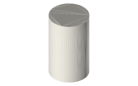
- Hole cutter: a cylinder at the hole Ø, insert length + 1 mm long, top face at z = 0: drop it into your model at the screw point and subtract it.
- Test boss: print one first to check the hole with your printer and plastic before printing the real part; a screw clearance hole runs through so you can test-tighten from below.
Sizes
| thread | insert_length_mm | hole_mm | hole_depth_mm | boss_od_mm |
|---|---|---|---|---|
| M2 | 3.0 | 3.2 | 4.0 | 5.8 |
| M2.5 | 4.0 | 4.0 | 5.0 | 7.2 |
| M3 | 5.7 | 4.0 | 6.7 | 7.2 |
| M3 | 3.0 | 4.0 | 4.0 | 7.2 |
| M3 | 4.0 | 4.4 | 5.0 | 7.6 |
| M4 | 8.1 | 5.7 | 9.1 | 9.9 |
| M4 | 4.0 | 5.7 | 5.0 | 9.9 |
| M5 | 9.5 | 6.5 | 10.5 | 11.7 |
| M5 | 5.8 | 6.5 | 6.8 | 11.7 |
| M6 | 12.7 | 8.1 | 13.7 | 14.7 |
| M8 | 12.7 | 9.7 | 13.7 | 18.7 |
| M10 | 12.7 | 12.0 | 13.7 | 24.0 |
| #2-56 | 3.2 | 3.2 | 4.2 | 5.8 |
| #4-40 | 5.7 | 4.0 | 6.7 | 7.2 |
| #4-40 | 3.6 | 4.0 | 4.6 | 7.2 |
| #6-32 | 7.1 | 4.8 | 8.1 | 8.4 |
| #6-32 | 3.8 | 4.8 | 4.8 | 8.4 |
| #8-32 | 8.2 | 5.7 | 9.2 | 9.9 |
| #8-32 | 4.7 | 5.7 | 5.7 | 9.9 |
| #10-24 | 9.5 | 6.5 | 10.5 | 11.7 |
| #10-32 | 9.5 | 6.5 | 10.5 | 11.7 |
| 1/4-20 | 12.7 | 8.1 | 13.7 | 14.7 |
| 1/4-20 | 6.4 | 8.1 | 7.4 | 14.7 |
| 5/16-18 | 12.7 | 9.7 | 13.7 | 18.7 |
| 3/8-16 | 12.7 | 12.0 | 13.7 | 24.0 |
| G1/8 | 12.7 | 12.0 | 13.7 | 24.0 |
Where the files are
Other publishers' files are linked, not hosted. "verify" = check the license at the link before commercial use.
| CNC Kitchen | Threaded insert dimensions and design guidelines poster: L, D1 (insert Ø), D2 (hole Ø), W (min wall); blind hole min. L + 1 mm | maker's sheet; dimensions cited, nothing copied |
Free files
★ Free files 52 parts. Generated by Xem Studio from the standard; threads are plain cylinders at major diameter. CC BY 4.0. index.json
| hole-cutter-m2x3 | M2 × 3 hole cutter: Ø3.2 × 4 (subtract from your part, top at z = 0) | STEP · STL |
| test-boss-m2x3 | M2 × 3 test boss: Ø5.8 × 7, insert hole Ø3.2 × 4 on top, screw clearance through | STEP · STL |
| hole-cutter-m2_5x4 | M2.5 × 4 hole cutter: Ø4 × 5 (subtract from your part, top at z = 0) | STEP · STL |
| test-boss-m2_5x4 | M2.5 × 4 test boss: Ø7.2 × 8, insert hole Ø4 × 5 on top, screw clearance through | STEP · STL |
| hole-cutter-m3x5.7 | M3 × 5.7 hole cutter: Ø4 × 6.7 (subtract from your part, top at z = 0) | STEP · STL |
| test-boss-m3x5.7 | M3 × 5.7 test boss: Ø7.2 × 9.7, insert hole Ø4 × 6.7 on top, screw clearance through | STEP · STL |
| hole-cutter-m3x3 | M3 × 3 hole cutter: Ø4 × 4 (subtract from your part, top at z = 0) | STEP · STL |
| test-boss-m3x3 | M3 × 3 test boss: Ø7.2 × 7, insert hole Ø4 × 4 on top, screw clearance through | STEP · STL |
| hole-cutter-m3x4 | M3 × 4 hole cutter: Ø4.4 × 5 (subtract from your part, top at z = 0) | STEP · STL |
| test-boss-m3x4 | M3 × 4 test boss: Ø7.6 × 8, insert hole Ø4.4 × 5 on top, screw clearance through | STEP · STL |
| hole-cutter-m4x8.1 | M4 × 8.1 hole cutter: Ø5.7 × 9.1 (subtract from your part, top at z = 0) | STEP · STL |
| test-boss-m4x8.1 | M4 × 8.1 test boss: Ø9.9 × 12.1, insert hole Ø5.7 × 9.1 on top, screw clearance through | STEP · STL |
| hole-cutter-m4x4 | M4 × 4 hole cutter: Ø5.7 × 5 (subtract from your part, top at z = 0) | STEP · STL |
| test-boss-m4x4 | M4 × 4 test boss: Ø9.9 × 8, insert hole Ø5.7 × 5 on top, screw clearance through | STEP · STL |
| hole-cutter-m5x9.5 | M5 × 9.5 hole cutter: Ø6.5 × 10.5 (subtract from your part, top at z = 0) | STEP · STL |
| test-boss-m5x9.5 | M5 × 9.5 test boss: Ø11.7 × 13.5, insert hole Ø6.5 × 10.5 on top, screw clearance through | STEP · STL |
| hole-cutter-m5x5.8 | M5 × 5.8 hole cutter: Ø6.5 × 6.8 (subtract from your part, top at z = 0) | STEP · STL |
| test-boss-m5x5.8 | M5 × 5.8 test boss: Ø11.7 × 9.8, insert hole Ø6.5 × 6.8 on top, screw clearance through | STEP · STL |
| hole-cutter-m6x12.7 | M6 × 12.7 hole cutter: Ø8.1 × 13.7 (subtract from your part, top at z = 0) | STEP · STL |
| test-boss-m6x12.7 | M6 × 12.7 test boss: Ø14.7 × 16.7, insert hole Ø8.1 × 13.7 on top, screw clearance through | STEP · STL |
| hole-cutter-m8x12.7 | M8 × 12.7 hole cutter: Ø9.7 × 13.7 (subtract from your part, top at z = 0) | STEP · STL |
| test-boss-m8x12.7 | M8 × 12.7 test boss: Ø18.7 × 16.7, insert hole Ø9.7 × 13.7 on top, screw clearance through | STEP · STL |
| hole-cutter-m10x12.7 | M10 × 12.7 hole cutter: Ø12 × 13.7 (subtract from your part, top at z = 0) | STEP · STL |
| test-boss-m10x12.7 | M10 × 12.7 test boss: Ø24.0 × 16.7, insert hole Ø12 × 13.7 on top, screw clearance through | STEP · STL |
| hole-cutter-2-56x3.2 | #2-56 × 3.2 hole cutter: Ø3.2 × 4.2 (subtract from your part, top at z = 0) | STEP · STL |
| test-boss-2-56x3.2 | #2-56 × 3.2 test boss: Ø5.8 × 7.2, insert hole Ø3.2 × 4.2 on top, screw clearance through | STEP · STL |
| hole-cutter-4-40x5.7 | #4-40 × 5.7 hole cutter: Ø4 × 6.7 (subtract from your part, top at z = 0) | STEP · STL |
| test-boss-4-40x5.7 | #4-40 × 5.7 test boss: Ø7.2 × 9.7, insert hole Ø4 × 6.7 on top, screw clearance through | STEP · STL |
| hole-cutter-4-40x3.6 | #4-40 × 3.6 hole cutter: Ø4 × 4.6 (subtract from your part, top at z = 0) | STEP · STL |
| test-boss-4-40x3.6 | #4-40 × 3.6 test boss: Ø7.2 × 7.6, insert hole Ø4 × 4.6 on top, screw clearance through | STEP · STL |
| hole-cutter-6-32x7.1 | #6-32 × 7.1 hole cutter: Ø4.8 × 8.1 (subtract from your part, top at z = 0) | STEP · STL |
| test-boss-6-32x7.1 | #6-32 × 7.1 test boss: Ø8.4 × 11.1, insert hole Ø4.8 × 8.1 on top, screw clearance through | STEP · STL |
| hole-cutter-6-32x3.8 | #6-32 × 3.8 hole cutter: Ø4.8 × 4.8 (subtract from your part, top at z = 0) | STEP · STL |
| test-boss-6-32x3.8 | #6-32 × 3.8 test boss: Ø8.4 × 7.8, insert hole Ø4.8 × 4.8 on top, screw clearance through | STEP · STL |
| hole-cutter-8-32x8.2 | #8-32 × 8.2 hole cutter: Ø5.7 × 9.2 (subtract from your part, top at z = 0) | STEP · STL |
| test-boss-8-32x8.2 | #8-32 × 8.2 test boss: Ø9.9 × 12.2, insert hole Ø5.7 × 9.2 on top, screw clearance through | STEP · STL |
| hole-cutter-8-32x4.7 | #8-32 × 4.7 hole cutter: Ø5.7 × 5.7 (subtract from your part, top at z = 0) | STEP · STL |
| test-boss-8-32x4.7 | #8-32 × 4.7 test boss: Ø9.9 × 8.7, insert hole Ø5.7 × 5.7 on top, screw clearance through | STEP · STL |
| hole-cutter-10-24x9.5 | #10-24 × 9.5 hole cutter: Ø6.5 × 10.5 (subtract from your part, top at z = 0) | STEP · STL |
| test-boss-10-24x9.5 | #10-24 × 9.5 test boss: Ø11.7 × 13.5, insert hole Ø6.5 × 10.5 on top, screw clearance through | STEP · STL |
| hole-cutter-10-32x9.5 | #10-32 × 9.5 hole cutter: Ø6.5 × 10.5 (subtract from your part, top at z = 0) | STEP · STL |
| test-boss-10-32x9.5 | #10-32 × 9.5 test boss: Ø11.7 × 13.5, insert hole Ø6.5 × 10.5 on top, screw clearance through | STEP · STL |
| hole-cutter-1-4-20x12.7 | 1/4-20 × 12.7 hole cutter: Ø8.1 × 13.7 (subtract from your part, top at z = 0) | STEP · STL |
| test-boss-1-4-20x12.7 | 1/4-20 × 12.7 test boss: Ø14.7 × 16.7, insert hole Ø8.1 × 13.7 on top, screw clearance through | STEP · STL |
| hole-cutter-1-4-20x6.4 | 1/4-20 × 6.4 hole cutter: Ø8.1 × 7.4 (subtract from your part, top at z = 0) | STEP · STL |
| test-boss-1-4-20x6.4 | 1/4-20 × 6.4 test boss: Ø14.7 × 10.4, insert hole Ø8.1 × 7.4 on top, screw clearance through | STEP · STL |
| hole-cutter-5-16-18x12.7 | 5/16-18 × 12.7 hole cutter: Ø9.7 × 13.7 (subtract from your part, top at z = 0) | STEP · STL |
| test-boss-5-16-18x12.7 | 5/16-18 × 12.7 test boss: Ø18.7 × 16.7, insert hole Ø9.7 × 13.7 on top, screw clearance through | STEP · STL |
| hole-cutter-3-8-16x12.7 | 3/8-16 × 12.7 hole cutter: Ø12 × 13.7 (subtract from your part, top at z = 0) | STEP · STL |
| test-boss-3-8-16x12.7 | 3/8-16 × 12.7 test boss: Ø24.0 × 16.7, insert hole Ø12 × 13.7 on top, screw clearance through | STEP · STL |
| hole-cutter-g1-8x12.7 | G1/8 × 12.7 hole cutter: Ø12 × 13.7 (subtract from your part, top at z = 0) | STEP · STL |
| test-boss-g1-8x12.7 | G1/8 × 12.7 test boss: Ø24.0 × 16.7, insert hole Ø12 × 13.7 on top, screw clearance through | STEP · STL |
Plain text: sheet.txt · JSON: /api/geometry?object=heat-set-insert-holes
Fits with
Free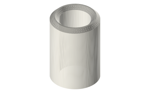 Heat-set threaded inserts, metric: M2 to M10, standard, short and Voron (CNC Kitchen sizes)12 sizes★ 12 filesFree
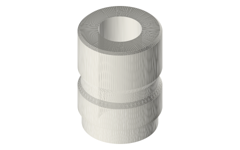 Heat-set threaded inserts, inch: #2-56 to 3/8-16 and G1/8 (CNC Kitchen sizes)14 sizes★ 14 filesFree
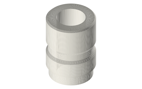 Heat-set threaded inserts, ruthex RX series: M2 to M8 and #2-56 to 3/8-1617 sizes★ 17 files
Questions
Why one more millimetre of depth?
Plastic melted by the insert flows ahead of it; the extra depth gives it somewhere to go so the insert seats flush.