 Xem Studiomeasured geometry
Library › Stirling engines › Drives & mechanisms ·
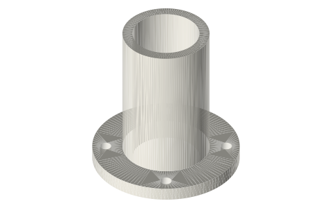
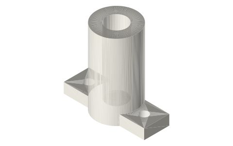
Flanged power cylinder liner Ø16, 20, 25, 30
What are the dimensions of a flanged power cylinder for a Stirling engine? · Hardware · basis: Bore 16–30, 3 mm wall, flange Ø(D + 24) × 4 with 4 × M3 clearance (Ø3.4, ISO 273) on Ø(D + 16)
Long Earth Society build part. The power piston and liner on the LES gamma. The engines
Exact dimensions. Every file is drawn at true size with no printing tolerance. The holes and pins that meet another part are listed below under Mating features, with the fit each joint needs; open those by your printer's or process's clearance before making the part. Mating features
- sizes
- 4 in table
Notes
- The power cylinder of the gamma engines when not using a syringe: a tube D bore × D + 6 outside, with a 4 thick flange of Ø(D + 24) at its base.
- Four Ø3.4 holes at 45°, 135°, 225° and 315° on a Ø(D + 16) circle take M3 screws to the base or head.
- The power piston of the same bore runs in it (fit: run); its swept volume at 12 mm stroke is in the table.
Sizes
| file | bore | outside | length | flange | hole circle | mL per 12 mm stroke |
|---|---|---|---|---|---|---|
| liner-16x40-flanged | 16 | 22 | 40 | 40 | 32 | 2.41 |
| liner-20x45-flanged | 20 | 26 | 45 | 44 | 36 | 3.77 |
| liner-25x50-flanged | 25 | 31 | 50 | 49 | 41 | 5.89 |
| liner-30x55-flanged | 30 | 36 | 55 | 54 | 46 | 8.48 |
Mating features
Drawn at the exact size. Open press, slide, run and socket features by your process's clearance; leave designed gaps and clamp fits as drawn.
| feature | exact | mates with | fit | files |
|---|---|---|---|---|
| liner bore | Ø16 / Ø20 / Ø25 / Ø30 | piston | run | liner-* |
| liner flange holes | Ø3.4 | M3 screw clearance | designed | liner-* |
Where the files are
Other publishers' files are linked, not hosted. "verify" = check the license at the link before commercial use.
| Wikipedia | Crosshead | web | CC BY-SA 4.0 (text) |
| Wikipedia | Piston | web | CC BY-SA 4.0 (text) |
| James R. Senft | Miniature Stirling engine piston fits (LTD book) | book | reference verify |
| Long Earth Society | Engine builds | web, video | LES site |
Free files
★ Free files 4 parts. Generated by Xem Studio from the standard; threads are plain cylinders at major diameter. CC BY 4.0. index.json
| liner-16x40-flanged | power cylinder liner Ø16 bore × 40, 3 wall, 4 mm flange Ø40 with 4 × M3 clearance (Ø3.4) on Ø32 | STEP · STL |
| liner-20x45-flanged | power cylinder liner Ø20 bore × 45, 3 wall, 4 mm flange Ø44 with 4 × M3 clearance (Ø3.4) on Ø36 | STEP · STL |
| liner-25x50-flanged | power cylinder liner Ø25 bore × 50, 3 wall, 4 mm flange Ø49 with 4 × M3 clearance (Ø3.4) on Ø41 | STEP · STL |
| liner-30x55-flanged | power cylinder liner Ø30 bore × 55, 3 wall, 4 mm flange Ø54 with 4 × M3 clearance (Ø3.4) on Ø46 | STEP · STL |
Plain text: sheet.txt · JSON: /api/geometry?object=power-cylinder-liner
How it fits
Goes in or on
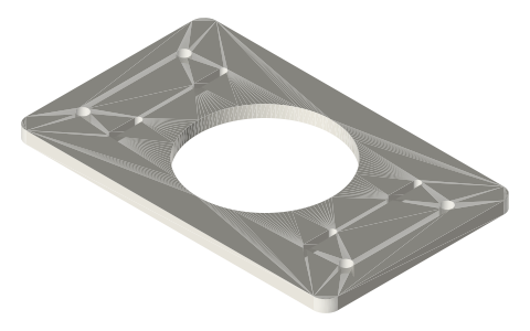 Base plate for 1.5, 2 and 3 in tri-clamp Stirling…flange on the base plate
Connects to
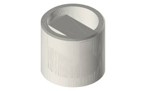 Power piston Ø16, 20, 25, 30 with Ø3 wrist-pin bosspiston of the same bore inside (run)
Alternatives
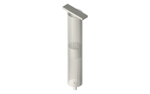 Plastic syringes 1–60 mL as pistons and cylinderssyringe barrel as the cylinder
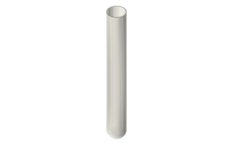 Borosilicate test tubes, 10×75 to 30×200 mmglass tube as the cylinder
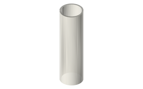 Free-piston cylinder liner Ø30 × 120 and Ø40 × 160Ø30 / Ø40 plain liners
Also needed
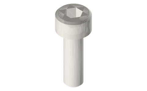 Socket head cap screws, M2–M84 × M3
In these build lists
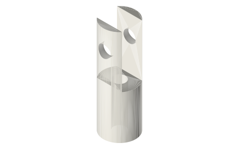
Gamma Stirling, 2 in tri-clampHot spool with a shell displacer, a crank head that carries the crankshaft, the …You might also need
Questions
What power cylinder for a 2 in tri-clamp gamma?
Ø20 × 45: at 12 mm stroke it sweeps 3.77 mL, in range for the Ø46 × 90 displacer at 20 mm stroke.
What is the bolt pattern on the liner flange?
4 × Ø3.4 on a circle 16 mm larger than the bore (Ø36 for the Ø20 liner).