 Xem Studiomeasured geometry
Library › Stirling engines › Drives & mechanisms ·
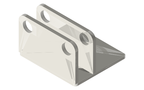
Rhombic frame head for the 2 in tri-clamp beta: gear-shaft walls on a clamp-on cap
What holds the gears of a rhombic drive on a 2 inch tri-clamp spool? · Hardware · basis: ISO 2852 cap face; 625 bearing (5 × 16 × 5) pockets on the rhombic gear centre distance 66; heights and planes from the rhombic kinematics in tools/rhombic_geom.py
Long Earth Society build part. The connectors between rods, cranks and drives on the LES engines. The engines
Exact dimensions. Every file is drawn at true size with no printing tolerance. The holes and pins that meet another part are listed below under Mating features, with the fit each joint needs; open those by your printer's or process's clearance before making the part. Mating features
- sizes
- 5 in table
Notes
- An ISO 2852 cap face for the 2 in ferrule, a Ø50.8 pedestal clear of the clamp, and a 96 × 87 × 4 platform at 14 mm with a Ø24 rod window on the spool axis.
- Two walls, 5 mm thick and 96 wide, stand on the platform behind the spool axis (y -31..-26 and -61..-56); each has two Ø16 through pockets for 625 bearings (fit: press) at x ±33, 62 mm above the face: the two Ø5 gear shafts, 66 mm apart, the meshing distance of the module 1.5 × 44 T gears.
- The gears hang in front of the front wall on the shaft ends; links and yokes are in front of them on the rod axis. At 62 mm the gears, the lower links and the lower yoke all stay above the platform through a full turn.
- The rear wall's shaft collars and the 1 mm spacers between gear hubs and front bearings hold each shaft axially.
Sizes
| feature | size_mm | position_mm |
|---|---|---|
| ISO 2852 face | 2 in (Ø64 rim) | z 0 |
| platform | 96 × 87 × 4 | z 14..18 |
| walls | 96 × 5, to z 75 | y -31..-26, -61..-56 |
| 625 pockets | Ø16 through | x ±33, z 62 |
| rod window | Ø24 | on the axis |
Mating features
Drawn at the exact size. Open press, slide, run and socket features by your process's clearance; leave designed gaps and clamp fits as drawn.
| feature | exact | mates with | fit | files |
|---|---|---|---|---|
| rhombic head face | ISO 2852 | ferrule face + Type B gasket | clamp | rhombic-frame-head-* |
| rhombic head bearing pockets | Ø16 through, 5 | 625 bearing (gear shafts) | press | rhombic-frame-head-* |
| rhombic head rod window | Ø24 | tube rod, plug stub, lower yoke boss (no contact) | designed | rhombic-frame-head-* |
Where the files are
Other publishers' files are linked, not hosted. "verify" = check the license at the link before commercial use.
| Long Earth Society | Tri-clamp Stirling engine builds | web, video | LES site |
Free files
★ Free files 1 parts. Generated by Xem Studio from the standard; threads are plain cylinders at major diameter. CC BY 4.0. index.json
| rhombic-frame-head-2in | 2 in rhombic frame head: ISO 2852 cap face, Ø50.8 pedestal to 14, 96 × 87 platform 14..18, two 5 mm walls (y -31..-26 and -61..-56 behind the spool axis) with Ø16 through pockets for 625 bearings at x ±33, 62 above the face; Ø24 rod window on the axis | STEP · STL |
Plain text: sheet.txt · JSON: /api/geometry?object=rhombic-frame-head
How it fits
Goes in or on
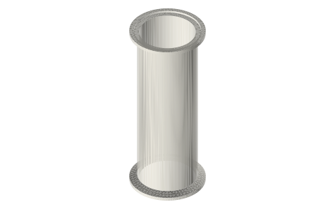 Tri-clamp spool, 1.5 and 2 inchISO 2852 face on the ferrule with a gasket
Connects to
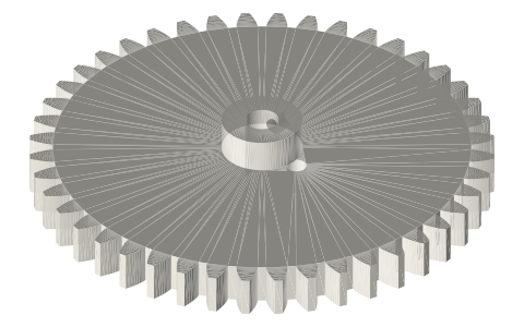 Rhombic drive crank gear, module 1.5, 44 T, 7 mm…gear shafts in the 625s, 66 apart
Also needed
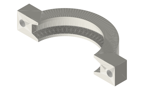 Tri-clamp clamp, two-boltclamp over the ferrule
 Ball bearings, 683 to 6210 and flanged F6xxfour 625s
In these build lists
Beta Stirling, rhombic drive, 2 in tri-clampDisplacer and piston in one bore, driven by two counter-rotating gears on a rhom…You might also need
Questions
How does the rhombic drive attach to a tri-clamp spool?
The frame head clamps on the spool's open ferrule like any cap; its two walls carry the two gear shafts in 625 bearings, 66 mm apart and 62 mm above the face.
Which bearings does the rhombic frame head take?
Four 625s (5 × 16 × 5), two per wall, flush in Ø16 through pockets.