 Xem Studiomeasured geometry
Library › Stirling engines › Tri-clamp engine parts ·
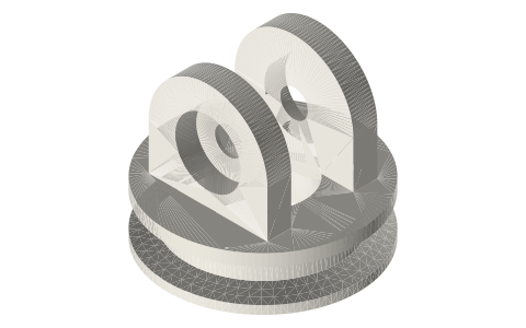
Tri-clamp crank frame: ISO 2852 cap with 608 towers for a Ø8 crankshaft, 1.5, 2 and 3 in
How do I mount a crankshaft on a tri-clamp spool? · Hardware · basis: ISO 2852 cap face; pedestal Ø = tube OD to clear the clamp; two 8 mm towers with Ø22 608 pockets, 21 mm apart, crank axis 32 / 34 / 40 mm above the face
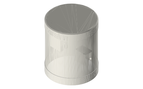
Long Earth Society build part. Full-bore pistons for the tri-clamp beta and alpha engines. The engines
Exact dimensions. Every file is drawn at true size with no printing tolerance. The holes and pins that meet another part are listed below under Mating features, with the fit each joint needs; open those by your printer's or process's clearance before making the part. Mating features
- sizes
- 3 in table
Notes
- A crank frame that clamps onto the open ferrule of a spool with a stock clamp and gasket, and holds a Ø8 crankshaft in two 608 bearings above it.
- Base: the 6 mm ISO 2852 cap, a pedestal the tube's OD (38.1 / 50.8 / 76.2) up to 14 mm so the clamp clears, and a Ø C3 plate 4 mm thick on top. A con-rod window Ø21 / Ø28 / Ø44 runs through the centre.
- Two towers 8 mm thick with rounded tops stand 21 mm apart; each has a Ø22 × 7 pocket for a 608 from the outside face, and the shaft hole between is Ø9.2 so the Ø8 shaft touches only the bearings.
- Crank axis 32 / 34 / 40 mm above the face for 1.5 / 2 / 3 in; overall height 47.7 / 54 / 60 mm.
Sizes
| spool_in | flange_od_mm | window_mm | crank_axis_mm | tower_gap_mm | bearing | overall_h_mm |
|---|---|---|---|---|---|---|
| 1.5 | 50.5 | 21 | 32 | 21 | 608 (Ø22) | 47.7 |
| 2 | 64.0 | 28 | 34 | 21 | 608 (Ø22) | 54.0 |
| 3 | 91.0 | 44 | 40 | 21 | 608 (Ø22) | 60.0 |
Mating features
Drawn at the exact size. Open press, slide, run and socket features by your process's clearance; leave designed gaps and clamp fits as drawn.
| feature | exact | mates with | fit | files |
|---|---|---|---|---|
| crank-frame bearing pockets | Ø22 | 608 bearing | press | crank-frame-* |
| crank-frame face | ISO 2852 | tri-clamp ferrule face + Type B gasket | clamp | crank-frame-* |
| crank-frame shaft clearance | Ø9.2 | Ø8 shaft (no contact; the 608s carry it) | designed | crank-frame-* |
Where the files are
Other publishers' files are linked, not hosted. "verify" = check the license at the link before commercial use.
| Long Earth Society | Tri-clamp Stirling engine builds | web, video | LES site |
| James R. Senft | An Introduction to Stirling Engines (piston fit and leakage) | book | Moriya Press verify |
| ASME | BPE tube dimensions (16 ga sanitary tube) | standard | ASME verify |
Free files
★ Free files 3 parts. Generated by Xem Studio from the standard; threads are plain cylinders at major diameter. CC BY 4.0. index.json
| crank-frame-1.5in | 1.5 in crank frame: ISO 2852 cap face (clamps to the spool with a stock clamp), Ø21 con-rod window, two towers with 608 pockets for a Ø8 crankshaft 32 mm above the face, 21 mm between towers | STEP · STL |
| crank-frame-2in | 2 in crank frame: ISO 2852 cap face (clamps to the spool with a stock clamp), Ø28 con-rod window, two towers with 608 pockets for a Ø8 crankshaft 34 mm above the face, 21 mm between towers | STEP · STL |
| crank-frame-3in | 3 in crank frame: ISO 2852 cap face (clamps to the spool with a stock clamp), Ø44 con-rod window, two towers with 608 pockets for a Ø8 crankshaft 40 mm above the face, 21 mm between towers | STEP · STL |
Plain text: sheet.txt · JSON: /api/geometry?object=tri-clamp-crank-frame
How it fits
Goes in or on
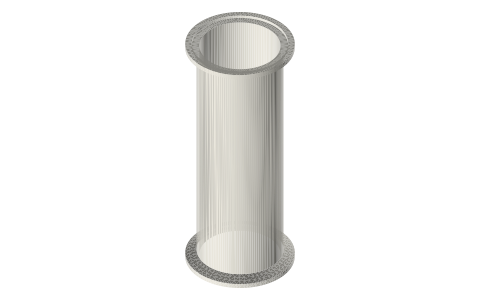 Tri-clamp spool, 1.5 and 2 inchISO 2852 face on the open ferrule
Connects to
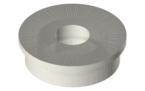 608 ball bearing608 in each Ø22 × 7 pocket
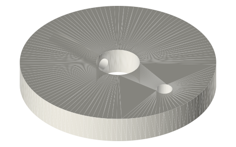 Tri-clamp crank webtwo webs on the Ø8 shaft between the towers
Also needed
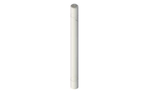 Metric shafts Ø3 to Ø10 with D-flats and clip…Ø8 shaft and collar
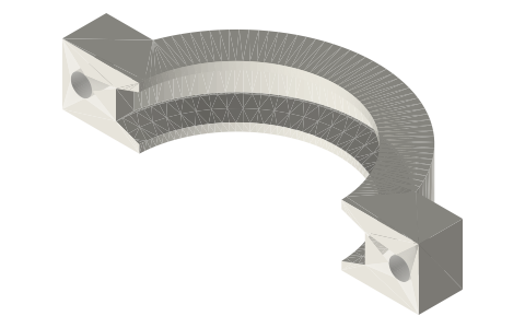 Tri-clamp clamp, two-boltclamp and gasket on the face
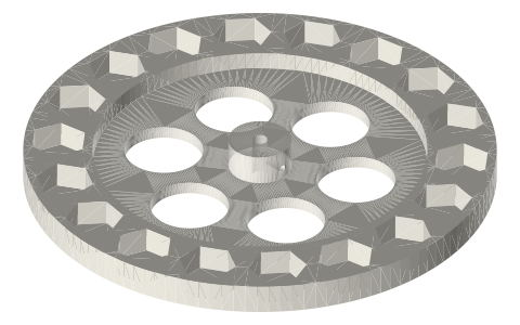 Flywheels Ø100–Ø200 with hex-nut rim pocketsØ8-hub flywheel outside a tower
You might also need
Questions
How do I put a crankshaft on a tri-clamp cylinder?
Clamp the crank frame to the open ferrule; a Ø8 shaft runs in two 608s in its towers, 34 mm above the face on the 2 in frame.
How wide is the gap between the crank-frame towers?
21 mm: crank web, con-rod, crank web (5 mm each) with 1 mm gaps.
Does the shaft touch the frame?
No: the shaft hole is Ø9.2; the Ø8 shaft runs only in the 608s.