 Xem Studiomeasured geometry
Library › Stirling engines › Free-piston ·
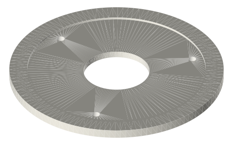
Flexure ring for the displacer stack: Ø76, Ø96 and Ø116 with Ø60, Ø80 and Ø100 seats
What holds the displacer's flexure stack above a free-piston head? · Hardware · basis: Ring Ø = flexure OD + 16, 4 mm thick, flexure-OD × 1 seat, 3 × Ø3.4 on the 0.88 × OD circle (same as the flexure head)
Long Earth Society build part. The connecting parts of the tri-clamp free-piston engine. The engines
Exact dimensions. Every file is drawn at true size with no printing tolerance. The holes and pins that meet another part are listed below under Mating features, with the fit each joint needs; open those by your printer's or process's clearance before making the part. Mating features
- sizes
- 3 in table
Notes
- The ring that carries the displacer's flexure stack (stack B) on three M3 standoffs above the flexure head.
- Ø76 / Ø96 / Ø116 × 4 mm for Ø60 / Ø80 / Ø100 leaves, with a seat the flexure OD × 1 mm deep, a centre window hub + 6 (Ø19.2 / Ø23.6 / Ø28), and three Ø3.4 holes on the same circle as the head (Ø52.8 / Ø70.4 / Ø88).
Sizes
| flexure_od_mm | ring_od_mm | thickness_mm | seat_mm | window_mm | hole_circle_mm |
|---|---|---|---|---|---|
| 60 | 76 | 4 | Ø60 × 1 | 19.2 | 52.8 |
| 80 | 96 | 4 | Ø80 × 1 | 23.6 | 70.4 |
| 100 | 116 | 4 | Ø100 × 1 | 28.0 | 88.0 |
Mating features
Drawn at the exact size. Open press, slide, run and socket features by your process's clearance; leave designed gaps and clamp fits as drawn.
| feature | exact | mates with | fit | files |
|---|---|---|---|---|
| flexure pocket in the head / ring | flexure OD | spiral flexure leaf rim | slide | fp-flexure-* |
| rim holes (head, ring) | Ø3.4 | M3 screw clearance | designed | fp-flexure-* |
| head / ring window | hub + 12 (Ø29.6 on Ø80) | hub collars and their pinch-screw heads (no contact) | designed | fp-flexure-* |
Where the files are
Other publishers' files are linked, not hosted. "verify" = check the license at the link before commercial use.
| NASA NTRS | Free-piston Stirling convertor flexure bearing development and life testing | US Government work | |
| Long Earth Society | Tri-clamp Stirling engine builds | web, video | LES site |
| Wikipedia | Free-piston engine | web | CC BY-SA 4.0 (text) |
Free files
★ Free files 3 parts. Generated by Xem Studio from the standard; threads are plain cylinders at major diameter. CC BY 4.0. index.json
| fp-flexure-ring-60 | Ø76 × 4 ring for stack B (displacer rod) on 3 × M3 standoffs above the head: Ø60 × 1 flexure pocket, Ø25.2 window, 3 × Ø3.4 | STEP · STL |
| fp-flexure-ring-80 | Ø96 × 4 ring for stack B (displacer rod) on 3 × M3 standoffs above the head: Ø80 × 1 flexure pocket, Ø29.6 window, 3 × Ø3.4 | STEP · STL |
| fp-flexure-ring-100 | Ø116 × 4 ring for stack B (displacer rod) on 3 × M3 standoffs above the head: Ø100 × 1 flexure pocket, Ø34 window, 3 × Ø3.4 | STEP · STL |
Plain text: sheet.txt · JSON: /api/geometry?object=tri-clamp-flexure-ring
How it fits
Connects to
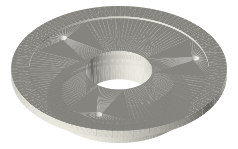 Tri-clamp flexure head3 × M3 standoffs on the shared hole circle
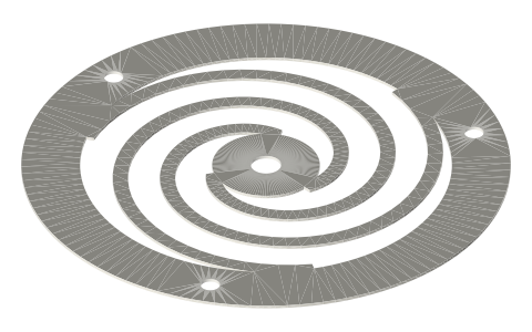 Planar spiral flexure bearing leavesleaf rim in the seat
Also needed
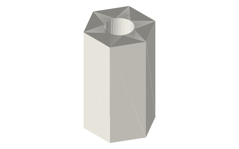 Threaded standoffs, M2.5 and M3M3 standoffs
In these build lists
Free-piston Stirling, 2 in tri-clampNo crank: piston and displacer each hang on a stack of spiral flexures, with a t…You might also need
Questions
How far is the flexure ring above the head?
Set by the M3 standoffs between them; the stack-B height sets the displacer's moving mass and phase.
Which ring goes with the 2 inch head?
Fp-flexure-ring-80: Ø96 × 4 with the Ø80 seat.