 Xem Studiomeasured geometry
Library › Hardware › Tri-clamp caps & heads ·
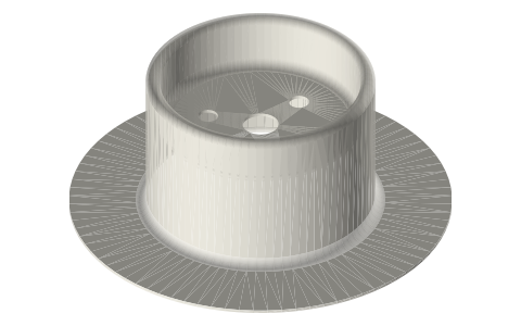
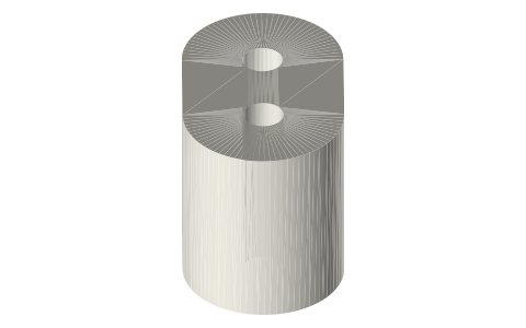
2 in tri-clamp rolling-diaphragm head with cylinder, rod guide and crank tower
What tri-clamp head holds a rolling diaphragm and its piston? · Hardware · basis: ISO 2852 face (flat, gasket groove), rim and 20° back cone as the flat end cap on this site; rolling-diaphragm bore, radii and stroke from the published 1.50 in size; 625 and 5 × 8 × 12 bushing sizes from their standards; crank geometry is a design value
Long Earth Society build part. The heart of my rolling-diaphragm engines: I clamp it on and the piston problem is gone. The engines
Exact dimensions. Every file is drawn at true size with no printing tolerance. The holes and pins that meet another part are listed below under Mating features, with the fit each joint needs; open those by your printer's or process's clearance before making the part. Mating features
- sizes
- 9 in table
Notes
- One part behind a standard 2 in clamp joint. Its clamped end is a standard ISO 2852 2 in face: flat from the 2 in bore out, the gasket groove on Ø56.5, the 2.85 mm rim and the 20° back cone, exactly as an end cap's (inside the 2 in bore it has a 1.6 mm seat pocket for the seat ring), so the standard clamp closes on it and it goes on any 2 in ferrule.
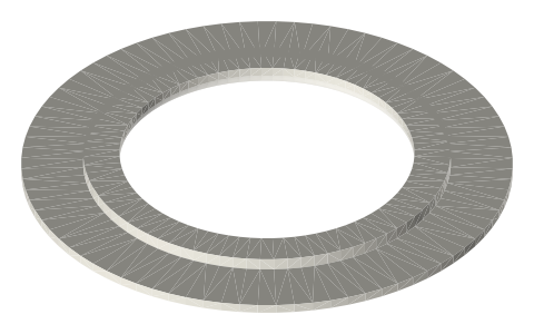
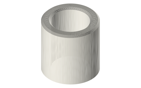
- The diaphragm's flange (0.51) takes the place of the gasket. Between the flange and the head sits the seat ring: 1.19 mm between the flange and the head's face and down into the head's seat pocket inside Ø47.5, so flange plus ring are the 1.7 mm of a Type B gasket's web and the clamp closes exactly as it does on a gasket. The ring carries the 1/16 in mouth radius the diaphragm wall rolls off, and its Ø38.10 bore runs on into the head's.
- Behind the ring: the Ø38.10 bore the diaphragm rolls in, down to a floor 49 mm from the clamp plane with four Ø6 vents so the back of the diaphragm is at air pressure; a Ø16 boss with an Ø8 seat for two 5 × 8 × 12 sleeve bushings that guide the Ø5 tube piston rod.
- A tower on −Y carries two 625 bearings (Ø16 × 5 pockets, 24 apart) on a Ø5 crankshaft 188 mm from the clamp plane: a 20 mm stroke crank disc on the shaft end, a conrod-80 down to the rod yoke. The flywheel goes on the far end.
- The same head goes on the 2 in cup of the beta (straight up) and on the branch of a standard 2 in tee in the Ringbom and gamma (sideways).
Sizes
| feature | value_mm |
|---|---|
| clamp face | ISO 2852 2 in, face plane 0.85 from the clamp plane |
| seat ring on the land | 1.19 |
| seat ring in the seat pocket | 2.79 |
| bore Ø | 38.1 |
| bore depth | 49.0 |
| bushing seat | Ø8 × 24 |
| bearing pockets | Ø16 × 5, y −26 and −50 |
| shaft axis | 188.0 |
| stroke | 20.0 |
Mating features
Drawn at the exact size. Open press, slide, run and socket features by your process's clearance; leave designed gaps and clamp fits as drawn.
| feature | exact | mates with | fit | files |
|---|---|---|---|---|
| clamp face | ISO 2852 2 in (flat Ø47.5–Ø64.0, gasket groove on Ø56.5 (1.6 deep, R1.2 bottom, 23° walls), rim 2.85, 20° back), face plane 0.85 from the clamp plane | 2 in clamp; seat ring and diaphragm flange in place of a gasket | clamp | rd-power-head* |
| seat pocket | Ø47.5 × 1.6 (inside the 2 in bore) | seat ring (fills it) | slide | rd-power-head* |
| cylinder bore | Ø38.10 from the seat-pocket floor to 49 | rolling diaphragm outer wall (piston 2.41 clear) | designed | rd-power-head* |
| seat ring OD in the pocket | Ø47.5 × 1.6 | power head seat pocket | slide | rd-seat-ring* |
| seat ring on the land | Ø56.5–Ø63.5 × 1.19 | power head land and the diaphragm flange (flange + ring = 1.7, a Type B web) | clamp | rd-seat-ring* |
| seat ring bore | Ø38.10, 1/16 in mouth radius | rolling diaphragm wall (rolls off the radius) | designed | rd-seat-ring* |
| bushing seat | Ø8 × 24 | two 5 × 8 × 12 sleeve bushings | press | all |
| bearing pockets | Ø16 × 5 (two) | 625 bearing | press | all |
| shaft passage | Ø8 | Ø5 crankshaft (no contact) | designed | all |
| floor vents | 4 × Ø6 | air (back of the diaphragm) | designed | all |
Where the files are
Other publishers' files are linked, not hosted. "verify" = check the license at the link before commercial use.
| ISO (via iTeh sample) | ISO 2852 clamp liners: face profile and flange / groove diameters | standard excerpt; dimensions are facts | |
| ASME | BPE Bioprocessing Equipment (clamp fitting dimensions, tube OD and wall) | standard | ASME; dimensions are facts verify |
| Marsh Bellofram | Rolling diaphragm design manual (2022): nomenclature, height formula, standard-size tables, hardware radii | publisher's manual; dimensions cited, nothing copied | |
| Long Earth Society | Engine builds | web, video | LES site |
Free files
★ Free files 2 parts. Generated by Xem Studio from the standard; threads are plain cylinders at major diameter. CC BY 4.0. index.json
| rd-power-head-2in | 2 in rolling-diaphragm power head: standard ISO 2852 2 in clamp face (flat from Ø47.5 to Ø64 with the gasket groove on Ø56.5, rim 2.85, 20° back cone; face plane 0.85 from the clamp plane), a 1.6 seat pocket inside Ø47.5, Ø38.10 bore from the pocket floor to 49, floor 6 with 4 × Ø6 vents, Ø16 boss with an Ø8 × 24 seat for two 5 × 8 × 12 bushings, crank tower with two Ø16 × 5 bearing pockets on the shaft axis 188 above the clamp plane | STEP · STL |
| rd-seat-ring-2in | diaphragm seat ring: Ø63.5 × 1.19 between the flange and the head's face, 2.79 thick inside Ø47.5 (fills the head's 1.6 seat pocket), bore Ø38.10 with the 1/16 in mouth radius | STEP · STL |
Plain text: sheet.txt · JSON: /api/geometry?object=tri-clamp-rolling-diaphragm-head-2in
Fits with
Questions
Does it fit a standard clamp?
Yes: its clamped end is a standard 2 in face, and flange plus seat ring are as thick as a gasket's web.
Where does the gasket go?
There is none at this joint: the diaphragm's flange is the seal, with the seat ring behind it.
Why the vents?
So the back of the diaphragm and the piston's skirt stay at air pressure; otherwise the space would act as a spring and pump through the bushings.