 Xem Studiomeasured geometry
Library › Stirling engines › Generators & instruments ·
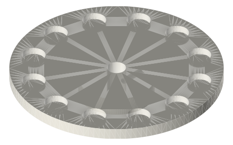
Axial-flux rotor plates: Ø90 with 12 magnets (Ø8 bore), Ø70 with 8 magnets (Ø5 bore)
How do I build a small axial flux generator rotor with neodymium magnets? · Hardware · basis: Coreless axial-flux layout: 12 poles on Ø90 or 8 poles on Ø70, pockets for Ø10 × 3 disc magnets, hub sized to the Ø8 / Ø5 shaft
Long Earth Society build part. The flywheel alternator on the LES generator builds. The engines
Exact dimensions. Every file is drawn at true size with no printing tolerance. The holes and pins that meet another part are listed below under Mating features, with the fit each joint needs; open those by your printer's or process's clearance before making the part. Mating features
- sizes
- 2 in table
Notes
- The Ø90 rotor is a 5 mm plate with 12 pockets Ø10 × 3 deep on a Ø72 circle, a Ø32 × 8 hub underneath and a Ø8 bore through (13 mm overall).
- The Ø70 rotor has 8 pockets Ø10 × 3 on a Ø52 circle, a Ø26 × 8 hub and a Ø5 bore.
- A Ø2.5 radial hole (M3 tap drill) enters the hub 4 mm below the plate for a grub screw.
- Magnets alternate N-S around the ring; a second rotor facing it (N opposite S across the stator) doubles the flux.
- Frequency = rpm × poles / 120: 600 rpm on the 12-pole rotor is 60 Hz.
Sizes
| rotor | plate_mm | magnets | magnet_circle_mm | hub_mm | bore_mm |
|---|---|---|---|---|---|
| rotor-90-12x-10x3-b8 | Ø90 × 5 | 12 × Ø10×3 | 72 | Ø32 × 8 | 8 |
| rotor-70-8x-10x3-b5 | Ø70 × 5 | 8 × Ø10×3 | 52 | Ø26 × 8 | 5 |
Mating features
Drawn at the exact size. Open press, slide, run and socket features by your process's clearance; leave designed gaps and clamp fits as drawn.
| feature | exact | mates with | fit | files |
|---|---|---|---|---|
| rotor bore | Ø8 / Ø5 | shaft (M3 grub) | slide | rotor-* |
| magnet pockets | Ø10 × 3 | Ø10 × 3 disc magnet | press | rotor-* |
| grub hole | Ø2.5 | M3 tap drill | designed | rotor-* |
Where the files are
Other publishers' files are linked, not hosted. "verify" = check the license at the link before commercial use.
| Wikipedia | Axial flux motor | web | CC BY-SA 4.0 (text) |
| Wikipedia | Alternator | web | CC BY-SA 4.0 (text) |
| Hugh Piggott | A Wind Turbine Recipe Book (axial-flux alternator design) | web, PDF | Author's site verify |
| Long Earth Society | Engine and rig builds | web, video | LES site |
Free files
★ Free files 2 parts. Generated by Xem Studio from the standard; threads are plain cylinders at major diameter. CC BY 4.0. index.json
| rotor-90-12x-10x3-b8 | rotor plate Ø90 × 5: 12 pockets for Ø10 × 3 magnets (alternating poles) on a 66 mm circle, Ø8 bore hub with set screw; two face each other across the stator | STEP · STL |
| rotor-70-8x-10x3-b5 | rotor plate Ø70 × 5: 8 pockets for Ø10 × 3 magnets on a 46 mm circle, Ø5 bore hub with set screw | STEP · STL |
Plain text: sheet.txt · JSON: /api/geometry?object=axial-flux-rotor
How it fits
Parts that fit it
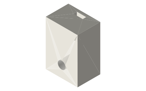 Hall sensor mount for TO-92Sfaces a rotor magnet: 12 pulses per revolution
Goes in or on
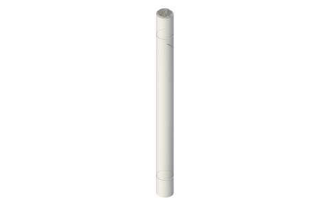 Metric shafts Ø3 to Ø10 with D-flats and clip…Ø8 / Ø5 bore on the shaft, M3 grub
Connects to
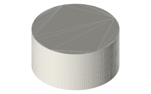 Neodymium disc magnets, common sizesØ10 × 3 magnets in the Ø10 × 3 pockets (press)
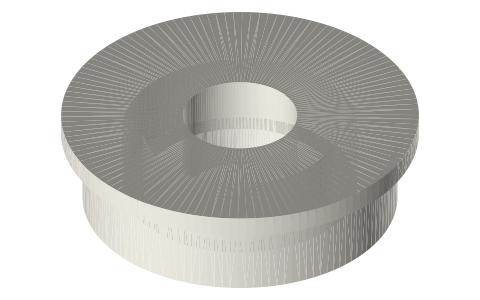 608 ball bearingthe Ø8 flywheel shaft runs in 608s
Also needed
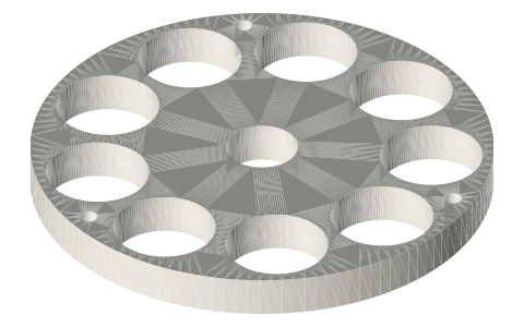 Axial-flux stator platescoils on the same Ø72 / Ø52 circle
You might also need
Questions
How many magnets for a small axial flux generator?
12 magnets with 9 coils (3-phase) on a Ø90 rotor, or 8 magnets with 6 coils on Ø70; poles alternate N-S.
What magnets fit the rotor?
Ø10 × 3 disc magnets; the pockets are drawn Ø10 × 3 exact (press, see Mating features).
What frequency does it make?
Rpm × poles / 120: 60 Hz at 600 rpm on the 12-pole rotor.