 Xem Studiomeasured geometry
Library › Hardware › Stirling & thermoacoustic ·
Crank discs, connecting rods and flywheels for model engines
What stroke and flywheel size does a small Stirling engine need? · Hardware · basis: Parametric parts sized for 3 mm crank pins, 623 bearings (3 × 10 × 4) in the rod ends, and 5 / 8 mm shafts; proportions from the Long Earth Society tri-clamp engines
Long Earth Society build part. The crank train from the LES tri-clamp Stirling builds, parametrized. The engines · all LES parts
- sizes
- 3 in table
Notes
- Crank disc: pin hole at stroke/2 from the bore; 3 mm dowel pin pressed in (2.95 mm hole in metal, 3.2 mm printed then reamed). Set screw locks the disc to a 5 mm shaft.
- Con-rod: 10.2 mm pockets take a 623 bearing at each end so the rod runs on balls, not plastic; centres 30–80 mm. Rod length ≥ 2 × stroke keeps the piston side-load low.
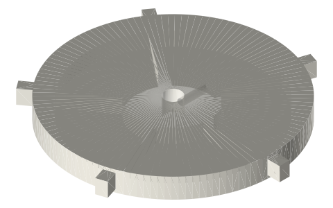
- Flywheel: energy ∝ D⁴, so go wide and thin: Ø100 × 10 mm in PLA with a brass rim insert outruns Ø60 solid. Balance by drilling the heavy side after the first run.
- Long Earth Society: the 2 in tri-clamp engines use a 20 mm stroke, 50 mm rod and Ø100 flywheel on an 8 mm shaft in 608 bearings.
Sizes
| part | sizes | shaft_or_pin | bearing |
|---|---|---|---|
| crank disc | stroke 10, 15, 20, 25, 30 | Ø5 shaft, Ø3 pin | — |
| con-rod | centres 30, 40, 50, 60, 80 | Ø3 pins | 623 both ends |
| flywheel | Ø50, 80, 100, 120, 150 × 10 | Ø5 (50) / Ø8 | 608 on the shaft |
Where the files are
Other publishers' files are linked, not hosted. "verify" = check the license at the link before commercial use.
| Wikipedia | Crank (mechanism) | web | CC BY-SA 4.0 (text) |
| Wikipedia | Flywheel | web | CC BY-SA 4.0 (text) |
| Wikipedia | Stirling engine | web | CC BY-SA 4.0 (text) |
| Long Earth Society | Engine builds that use these parts (videos and write-ups) | web, video | LES site |
Free files
★ Free files 15 parts. Generated by Xem Studio from the standard; threads are plain cylinders at major diameter. CC BY 4.0. index.json
| crank-disc-stroke10 | crank disc for 10 mm stroke (pin at 5.0 mm), Ø5 bore, M3 set screw, Ø3 pin hole | STEP · STL |
| crank-disc-stroke15 | crank disc for 15 mm stroke (pin at 7.5 mm), Ø5 bore, M3 set screw, Ø3 pin hole | STEP · STL |
| crank-disc-stroke20 | crank disc for 20 mm stroke (pin at 10.0 mm), Ø5 bore, M3 set screw, Ø3 pin hole | STEP · STL |
| crank-disc-stroke25 | crank disc for 25 mm stroke (pin at 12.5 mm), Ø5 bore, M3 set screw, Ø3 pin hole | STEP · STL |
| crank-disc-stroke30 | crank disc for 30 mm stroke (pin at 15.0 mm), Ø5 bore, M3 set screw, Ø3 pin hole | STEP · STL |
| conrod-30 | connecting rod, 30 mm centres, 10.2 mm pockets for 623 bearings both ends, 5 thick | STEP · STL |
| conrod-40 | connecting rod, 40 mm centres, 10.2 mm pockets for 623 bearings both ends, 5 thick | STEP · STL |
| conrod-50 | connecting rod, 50 mm centres, 10.2 mm pockets for 623 bearings both ends, 5 thick | STEP · STL |
| conrod-60 | connecting rod, 60 mm centres, 10.2 mm pockets for 623 bearings both ends, 5 thick | STEP · STL |
| conrod-80 | connecting rod, 80 mm centres, 10.2 mm pockets for 623 bearings both ends, 5 thick | STEP · STL |
| flywheel-50 | spoked flywheel Ø50 × 10, Ø5 bore, M3 set screw | STEP · STL |
| flywheel-80 | spoked flywheel Ø80 × 10, Ø8 bore, M3 set screw | STEP · STL |
| flywheel-100 | spoked flywheel Ø100 × 10, Ø8 bore, M3 set screw | STEP · STL |
| flywheel-120 | spoked flywheel Ø120 × 10, Ø8 bore, M3 set screw | STEP · STL |
| flywheel-150 | spoked flywheel Ø150 × 10, Ø8 bore, M3 set screw | STEP · STL |
Plain text: sheet.txt · JSON: /api/geometry?object=crank-conrod-flywheel-kit
Fits with
Questions
How big should a Stirling engine flywheel be?
For a 2 in (50 mm bore) displacer engine, Ø100 × 10 mm is a good start; energy stored goes with the fourth power of diameter, so diameter beats thickness.
What bearings go in a model engine connecting rod?
623 (3 × 10 × 4) at each end on 3 mm pins; the rod pocket is 10.2 mm in a print.
How do I set the stroke on a crank disc?
Stroke = 2 × pin offset. The discs here have the pin at 5, 7.5, 10, 12.5 and 15 mm for 10–30 mm strokes.