 Xem Studiomeasured geometry
Library › Hardware › Stirling & thermoacoustic ·
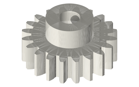
Spur gears, involute 20°: module 0.5, 1 and 2, 12–60 teeth
What is the outer diameter and centre distance for module 1 spur gears? · Hardware · basis: ISO 53 / DIN 867 basic rack, 20° pressure angle, standard addendum (1 m) and dedendum (1.25 m); true involute flanks generated point by point
Long Earth Society build part. Used in the LES displacer drive and generator reduction builds. The engines · all LES parts
- sizes
- 21 in table
Notes
- Pitch diameter = module × teeth; outer diameter = module × (teeth + 2); centre distance between two gears = module × (N1 + N2) / 2. Module 1, 20T + 40T → 30 mm centres.
- Printed gears: module 1 is the practical floor on an FDM printer with a 0.4 mm nozzle; module 0.5 needs resin. Add 0.1–0.15 mm to the centre distance for backlash on printed pairs.
- Bores are plain; hubs carry an M3 set-screw hole. Pair with the 623/625 bearings and 3/5 mm dowels in the library for a crank train.
- Long Earth Society: gear trains for Stirling displacer drives and the 2:1 reduction on the flywheel-driven generator builds.
Sizes
| module | teeth | pitch_dia_mm | outer_dia_mm | root_dia_mm | face_mm | bore_mm |
|---|---|---|---|---|---|---|
| 1 | 12 | 12.0 | 14.0 | 9.5 | 6 | 3 |
| 1 | 15 | 15.0 | 17.0 | 12.5 | 6 | 3 |
| 1 | 16 | 16.0 | 18.0 | 13.5 | 6 | 4 |
| 1 | 20 | 20.0 | 22.0 | 17.5 | 6 | 5 |
| 1 | 24 | 24.0 | 26.0 | 21.5 | 6 | 5 |
| 1 | 30 | 30.0 | 32.0 | 27.5 | 6 | 5 |
| 1 | 36 | 36.0 | 38.0 | 33.5 | 6 | 6 |
| 1 | 40 | 40.0 | 42.0 | 37.5 | 6 | 6 |
| 1 | 48 | 48.0 | 50.0 | 45.5 | 6 | 8 |
| 1 | 60 | 60.0 | 62.0 | 57.5 | 6 | 8 |
| 0.5 | 16 | 8.0 | 9.0 | 6.75 | 4 | 2 |
| 0.5 | 20 | 10.0 | 11.0 | 8.75 | 4 | 2 |
| 0.5 | 24 | 12.0 | 13.0 | 10.75 | 4 | 3 |
| 0.5 | 30 | 15.0 | 16.0 | 13.75 | 4 | 3 |
| 0.5 | 40 | 20.0 | 21.0 | 18.75 | 4 | 3 |
| 0.5 | 60 | 30.0 | 31.0 | 28.75 | 4 | 4 |
| 2 | 12 | 24.0 | 28.0 | 19.0 | 10 | 5 |
| 2 | 15 | 30.0 | 34.0 | 25.0 | 10 | 6 |
| 2 | 20 | 40.0 | 44.0 | 35.0 | 10 | 8 |
| 2 | 30 | 60.0 | 64.0 | 55.0 | 10 | 8 |
| 2 | 40 | 80.0 | 84.0 | 75.0 | 10 | 10 |
Where the files are
Other publishers' files are linked, not hosted. "verify" = check the license at the link before commercial use.
| Wikipedia | Involute gear | web | CC BY-SA 4.0 (text) |
| Wikipedia | Gear | web | CC BY-SA 4.0 (text) |
| KHK Gears | Gear technical reference (module, pressure angle, formulas) | web, PDF | KHK site terms verify |
| Long Earth Society | Engine builds that use these parts (videos and write-ups) | web, video | LES site |
Free files
★ Free files 21 parts. Generated by Xem Studio from the standard; threads are plain cylinders at major diameter. CC BY 4.0. index.json
| gear-m1-12t-b3 | module 1, 12 teeth, 20° PA, 6 mm face, Ø3 bore | STEP · STL |
| gear-m1-15t-b3 | module 1, 15 teeth, 20° PA, 6 mm face, Ø3 bore, hub with M3 set screw | STEP · STL |
| gear-m1-16t-b4 | module 1, 16 teeth, 20° PA, 6 mm face, Ø4 bore, hub with M3 set screw | STEP · STL |
| gear-m1-20t-b5 | module 1, 20 teeth, 20° PA, 6 mm face, Ø5 bore, hub with M3 set screw | STEP · STL |
| gear-m1-24t-b5 | module 1, 24 teeth, 20° PA, 6 mm face, Ø5 bore, hub with M3 set screw | STEP · STL |
| gear-m1-30t-b5 | module 1, 30 teeth, 20° PA, 6 mm face, Ø5 bore, hub with M3 set screw | STEP · STL |
| gear-m1-36t-b6 | module 1, 36 teeth, 20° PA, 6 mm face, Ø6 bore, hub with M3 set screw | STEP · STL |
| gear-m1-40t-b6 | module 1, 40 teeth, 20° PA, 6 mm face, Ø6 bore, hub with M3 set screw | STEP · STL |
| gear-m1-48t-b8 | module 1, 48 teeth, 20° PA, 6 mm face, Ø8 bore, hub with M3 set screw | STEP · STL |
| gear-m1-60t-b8 | module 1, 60 teeth, 20° PA, 6 mm face, Ø8 bore, hub with M3 set screw | STEP · STL |
| gear-m0.5-16t-b2 | module 0.5, 16 teeth, 20° PA, 4 mm face, Ø2 bore, hub with M3 set screw | STEP · STL |
| gear-m0.5-20t-b2 | module 0.5, 20 teeth, 20° PA, 4 mm face, Ø2 bore, hub with M3 set screw | STEP · STL |
| gear-m0.5-24t-b3 | module 0.5, 24 teeth, 20° PA, 4 mm face, Ø3 bore, hub with M3 set screw | STEP · STL |
| gear-m0.5-30t-b3 | module 0.5, 30 teeth, 20° PA, 4 mm face, Ø3 bore, hub with M3 set screw | STEP · STL |
| gear-m0.5-40t-b3 | module 0.5, 40 teeth, 20° PA, 4 mm face, Ø3 bore, hub with M3 set screw | STEP · STL |
| gear-m0.5-60t-b4 | module 0.5, 60 teeth, 20° PA, 4 mm face, Ø4 bore, hub with M3 set screw | STEP · STL |
| gear-m2-12t-b5 | module 2, 12 teeth, 20° PA, 10 mm face, Ø5 bore | STEP · STL |
| gear-m2-15t-b6 | module 2, 15 teeth, 20° PA, 10 mm face, Ø6 bore, hub with M3 set screw | STEP · STL |
| gear-m2-20t-b8 | module 2, 20 teeth, 20° PA, 10 mm face, Ø8 bore, hub with M3 set screw | STEP · STL |
| gear-m2-30t-b8 | module 2, 30 teeth, 20° PA, 10 mm face, Ø8 bore, hub with M3 set screw | STEP · STL |
| gear-m2-40t-b10 | module 2, 40 teeth, 20° PA, 10 mm face, Ø10 bore, hub with M3 set screw | STEP · STL |
Plain text: sheet.txt · JSON: /api/geometry?object=spur-gears-involute
Fits with
Questions
What is the outer diameter of a module 1 20 tooth gear?
22 mm (module × (teeth + 2)); pitch diameter 20 mm; root diameter 17.5 mm.
How do I calculate gear centre distance?
Module × (N1 + N2) / 2. Two module-1 gears with 20 and 40 teeth sit 30 mm apart; add 0.1–0.15 mm for printed backlash.
What is the smallest gear module that 3D prints well?
Module 1 with a 0.4 mm nozzle (tooth thickness 1.57 mm at the pitch line); module 0.8 is marginal; module 0.5 needs resin or a 0.2 mm nozzle.
What pressure angle are these gears?
20°, the modern standard; they mesh with any 20° involute gear of the same module, including brass stock gears.