 Xem Studiomeasured geometry
Library › Stirling engines › Drives & mechanisms ·
Crank discs for a Ø5 shaft, 10 to 30 mm stroke
What crank disc gives a 10–30 mm stroke on a 5 mm shaft? · Hardware · basis: Disc 6 thick, Ø5 bore, Ø3 pin hole at stroke / 2, M3 grub; disc Ø = max(30, stroke + 12)
Long Earth Society build part. The crank train from the LES tri-clamp Stirling builds, parametrized. The engines
Exact dimensions. Every file is drawn at true size with no printing tolerance. The holes and pins that meet another part are listed below under Mating features, with the fit each joint needs; open those by your printer's or process's clearance before making the part. Mating features
- sizes
- 5 in table
Notes
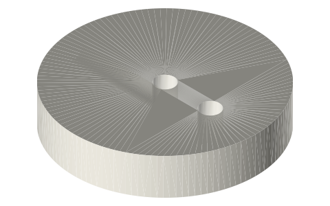
- A 6 mm disc with a Ø5 bore and a Ø3 crank-pin hole at half the stroke from the axis: 5.0, 7.5, 10.0, 12.5, 15.0 mm for 10–30 mm stroke.
- Disc Ø grows with the stroke: Ø30 (10 and 15), Ø32 (20), Ø37 (25), Ø42 (30).
- A radial Ø2.5 hole (M3 tap drill) at mid-thickness locks the disc to the shaft's D-flat.
- The crank pin is fixed in the disc and the con-rod's 623 turns on it; fits are under Mating features.
Sizes
| file | stroke | pin offset | disc Ø × t | bore |
|---|---|---|---|---|
| crank-disc-stroke10 | 10 | 5.0 | 30 × 6 | 5 |
| crank-disc-stroke15 | 15 | 7.5 | 30 × 6 | 5 |
| crank-disc-stroke20 | 20 | 10.0 | 32 × 6 | 5 |
| crank-disc-stroke25 | 25 | 12.5 | 37 × 6 | 5 |
| crank-disc-stroke30 | 30 | 15.0 | 42 × 6 | 5 |
Mating features
Drawn at the exact size. Open press, slide, run and socket features by your process's clearance; leave designed gaps and clamp fits as drawn.
| feature | exact | mates with | fit | files |
|---|---|---|---|---|
| crank-disc bore | Ø5 | Ø5 crankshaft (M3 set screw) | slide | crank-disc-* |
| crank-disc pin hole | Ø3 | Ø3 crank pin | press | crank-disc-* |
| crank-disc set-screw hole | Ø2.5 | M3 tap drill | designed | crank-disc-* |
Where the files are
Other publishers' files are linked, not hosted. "verify" = check the license at the link before commercial use.
| Wikipedia | Crank (mechanism) | web | CC BY-SA 4.0 (text) |
| Wikipedia | Flywheel | web | CC BY-SA 4.0 (text) |
| Wikipedia | Stirling engine | web | CC BY-SA 4.0 (text) |
| Long Earth Society | Engine builds that use these parts (videos and write-ups) | web, video | LES site |
Free files
★ Free files 5 parts. Generated by Xem Studio from the standard; threads are plain cylinders at major diameter. CC BY 4.0. index.json
| crank-disc-stroke10 | crank disc for 10 mm stroke (pin at 5.0 mm), Ø5 bore, M3 set screw, Ø3 pin hole | STEP · STL |
| crank-disc-stroke15 | crank disc for 15 mm stroke (pin at 7.5 mm), Ø5 bore, M3 set screw, Ø3 pin hole | STEP · STL |
| crank-disc-stroke20 | crank disc for 20 mm stroke (pin at 10.0 mm), Ø5 bore, M3 set screw, Ø3 pin hole | STEP · STL |
| crank-disc-stroke25 | crank disc for 25 mm stroke (pin at 12.5 mm), Ø5 bore, M3 set screw, Ø3 pin hole | STEP · STL |
| crank-disc-stroke30 | crank disc for 30 mm stroke (pin at 15.0 mm), Ø5 bore, M3 set screw, Ø3 pin hole | STEP · STL |
Plain text: sheet.txt · JSON: /api/geometry?object=crank-discs-5mm-bore
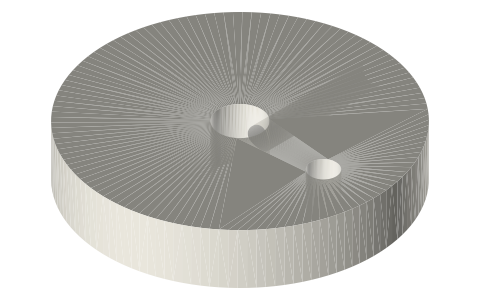
How it fits
Goes in or on
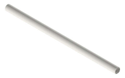 Crankshafts Ø3, Ø5 and Ø8 with full-length D-flatØ5 bore on the D-flat, M3 grub
Connects to
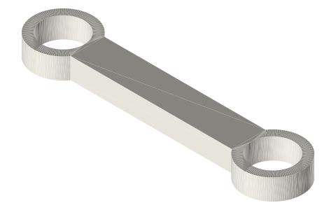 Connecting rods 30 to 80 mm centres with 623 pockets623 end on the Ø3 crank pin
Alternatives
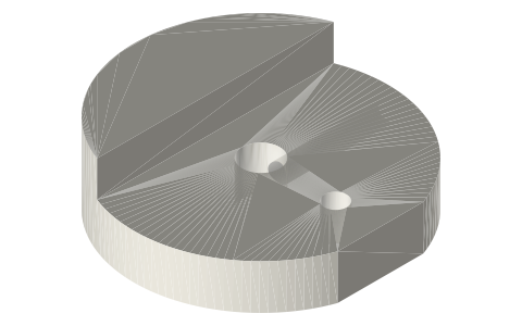 Counterweighted crank discs, Ø5 bore, 10 to 30 mm…same strokes with a counterweight
Also needed
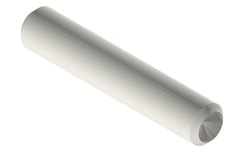 Crank and wrist pins Ø3 × 12, 16, 19, 20 and 23Ø3 crank pin
You might also need
Questions
How do I set the stroke on a crank disc?
Stroke = 2 × pin offset; these discs have the Ø3 pin hole at 5, 7.5, 10, 12.5 and 15 mm.
What stroke do the 2 in tri-clamp engines run?
20 mm: crank-disc-stroke20, Ø32 × 6.