 Xem Studiomeasured geometry
Library › Hardware › Stirling & thermoacoustic ·
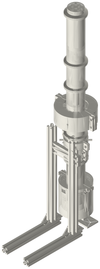
Moving-magnet linear alternator stator outside a 2 in tri-clamp spool: laminated two-tooth stator, one coil
How do I put a linear alternator outside a sealed tri-clamp tube? · Hardware · basis: Two-tooth moving-magnet topology (flux through the coil reverses as the magnet rows pass under the teeth); magnetic-circuit estimate with the magnets' published remanence; coil numbers from the winding window
Long Earth Society build part. The alternator of my free-piston generator. The engines
Exact dimensions. Every file is drawn at true size with no printing tolerance. The holes and pins that meet another part are listed below under Mating features, with the fit each joint needs; open those by your printer's or process's clearance before making the part. Mating features
- sizes
- 6 in table
Notes
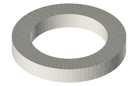
- The coil and its iron never touch the gas: they sit round the bored spool's 1.40 wall, which is not magnetic for this to work. Eight packs of radial laminations form two teeth on the tube and a yoke outside the coil; the flux from the S N N S magnet rows closes through one tooth, the yoke and the other, and reverses through the coil as the piston moves ±6 (the linear range: half a tooth).
- Estimate: gap flux density 0.42 T (magnets 1.31 T, 63 % of the carrier covered, 1.9 mm magnetic gap), 75 % of it linking the coil; dΦ/dx 0.096 Wb/m; with 300 turns of 0.71 mm wire: force constant 28.8 N/A (V·s/m), coil 3.40 Ω, inductance about 25 mH.
- At the design point (10 bar helium, ±5.0 mm, 45.1 Hz) it gives 40.8 V peak open circuit and 43.2 W into 11.5 Ω through a 500 µF series capacitor that cancels the coil's inductance (20 V peak across it). The load is the stroke control: never run it open-circuit.
- The flux in the laminations reverses at the running frequency: the plates must be thin and insulated from each other (drawn as 0.5 mm, as the pack envelope). The coil slides over S4's flange before the stack is clamped; the housing halves clamp the packs onto the tube with 4 × M4 × 20; the leads leave through the housing's hole between two packs.
Sizes
| item | value |
|---|---|
| teeth | 2 × 12 wide, slot 16 |
| packs | 8 × 43°, r 25.4–55 |
| coil | 300 t, 0.71 mm, 3.40 Ω |
| force constant | 28.8 N/A |
| inductance (est.) | 25 mH |
| linear range | ±6 mm |
Mating features
Drawn at the exact size. Open press, slide, run and socket features by your process's clearance; leave designed gaps and clamp fits as drawn.
| feature | exact | mates with | fit | files |
|---|---|---|---|---|
| teeth | r 25.4 (Ø50.8) | S4 tube OD | clamp | fpse-stator-pack* |
| OD | Ø110 | housing bore | clamp | fpse-stator-pack* |
| bobbin bore | Ø65 | slips over S4's Ø64 flange (no contact) | designed | fpse-bobbin* |
| ear holes | 2 × Ø4.5 each side | M4 × 20 and nuts (ISO 273 medium) | designed | fpse-stator-housing* |
| split | 1.0 total (0.5 per half) | the other half | clamp | fpse-stator-housing* |
| lead hole | Ø6 | coil leads | designed | fpse-stator-housing* |
Where the files are
Other publishers' files are linked, not hosted. "verify" = check the license at the link before commercial use.
| K&J Magnetics | Neodymium magnet specifications: N42 Br 1.30–1.32 T, density 7.4–7.5 g/cm³ | web | maker page; values are facts verify |
| Long Earth Society | Engine builds | web, video | LES site |
Free files
★ Free files 4 parts. Generated by Xem Studio from the standard; threads are plain cylinders at major diameter. CC BY 4.0. index.json
| fpse-stator-pack-43deg | stator pack: 43° of radial laminations 0.5 thick, two teeth r 25.4–50 at |z| 8–20, yoke r 50–55; drawn as its envelope; 8 round the tube | STEP · STL |
| fpse-bobbin-65 | bobbin Ø65 / Ø67 × 16, flanges Ø99 × 1: slips over S4's Ø64 flanges | STEP · STL |
| fpse-coil-300t | coil: 300 turns of 0.71 mm enamelled wire, the winding volume Ø67–Ø99 × 14 | STEP · STL |
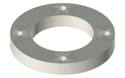
| fpse-stator-housing-half | stator housing half: shell r 55–58, end walls to r 34, ears with 2 × M4 each side, Ø6 lead hole; two halves clamp the packs onto the tube | STEP · STL |
Plain text: sheet.txt · JSON: /api/geometry?object=fpse-linear-alternator-stator
How it fits
In these build lists
Free-piston Stirling generator, 2 in tri-clamp…A real free-piston Stirling generator in standard 2 in sanitary fittings: closed…You might also need
Questions
Why outside the wall?
No wire through the pressure boundary and no coil in the gas: the vessel stays a sealed stack of tri-clamp parts. The price is 1.4 mm more magnetic gap than an inside coil.
What sets the stroke?
The load. The alternator's damping absorbs the engine's power; less load (higher resistance) lets the stroke grow. Keep a load connected whenever the engine is hot.