 Xem Studiomeasured geometry
Library › Hardware › Stirling & thermoacoustic ·
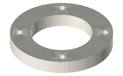
Free-piston power piston: Ø48 clearance-seal land, 40-magnet carrier, top plate and tube rod
What does the power piston of a moving-magnet free-piston generator look like? · Hardware · basis: Design values of the free-piston generator: running fit in the 48.00 bore over a 30 mm land; four magnet rows S N N S facing out; moving mass from the CAD at 7.9 g/cm³ and 7.5 g/cm³ (magnets)
Long Earth Society build part. The power piston of my free-piston generator. The engines
Exact dimensions. Every file is drawn at true size with no printing tolerance. The holes and pins that meet another part are listed below under Mating features, with the fit each joint needs; open those by your printer's or process's clearance before making the part. Mating features
- sizes
- 6 in table
Notes
- The piston is also the alternator's mover. Its lower 30 mm is the seal land, a running fit in the bored spool (the clearance seal between working space and bounce space); above it a Ø47 carrier (0.5 radial gap, no contact) holds 40 Ø12 × 3 disc magnets in four rows, faces out: S, N, N, S from the crown up.
- The carrier's body is the magnetic return between the rows, so it must be magnetically soft; the rest of the piston only has to be stiff and light. Moving mass with tube rod, collars and magnets: 918 g.
- The displacer rod runs through the Ø12 hub bore (a running fit 76 mm long, also a seal); the Ø23 crown pocket clears leaf B's collar. The top plate closes the carrier bore, carries the tube rod and vents the piston's inside to the bounce space.
- The tube rod carries the piston's two leaves (joints C and D) on four Ø28 collars.
Sizes
| part | size |
|---|---|
| seal land | Ø48.00 × 30 |
| carrier | Ø47 × 60, bore Ø30 |
| magnets | 40 × Ø12 × 3, rows S N N S at 14 pitch |
| hub bore | Ø12, 76 long |
| tube rod | Ø18 / Ø14 × 142.15 |
| moving mass | 918 g |
Mating features
Drawn at the exact size. Open press, slide, run and socket features by your process's clearance; leave designed gaps and clamp fits as drawn.
| feature | exact | mates with | fit | files |
|---|---|---|---|---|
| seal land | Ø48.00 × 30 | S4 bore Ø48.00 (clearance seal) | run | fpse-piston-48* |
| carrier OD | Ø47.0 | S4 bore (0.5 radial gap, no contact) | designed | fpse-piston-48* |
| magnet pockets | 40 × Ø12 × 3 radial | Ø12 × 3 disc magnets | press | fpse-piston-48* |
| hub bore | Ø12 × 76 | displacer rod (seal and guide) | run | fpse-piston-48* |
| carrier bore top | Ø30 × 4 | top plate | press | fpse-piston-48* |
| crown pocket | Ø23 × 6 | displacer collar Ø20 (no contact) | designed | fpse-piston-48* |
| bore | Ø18 | tube rod | press | fpse-piston-top* |
| OD | Ø18 | top plate bore, leaf hubs, collars | slide | fpse-tube-rod* |
| bore | Ø14 | displacer rod Ø12 (no contact) | designed | fpse-tube-rod* |
Where the files are
Other publishers' files are linked, not hosted. "verify" = check the license at the link before commercial use.
| K&J Magnetics | Neodymium magnet specifications: N42 Br 1.30–1.32 T, density 7.4–7.5 g/cm³ | web | maker page; values are facts verify |
| Long Earth Society | Engine builds | web, video | LES site |
Free files
★ Free files 3 parts. Generated by Xem Studio from the standard; threads are plain cylinders at major diameter. CC BY 4.0. index.json
| fpse-piston-48-40mag | piston body: seal land Ø48.00 × 30 (crown 8 with a Ø23 × 6 pocket, skirt bore Ø44), magnet carrier Ø47 × 60 (bore Ø30) with 4 rows × 10 radial pockets Ø12 × 3 at z 37, 51, 65, 79, hub tube Ø20 / Ø12 (the rod's running fit) | STEP · STL |
| fpse-piston-top-plate | piston top plate Ø30 × 4 in the carrier bore on the hub's end, Ø18 bore for the tube rod, 4 × Ø2 vents | STEP · STL |
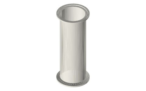
| fpse-tube-rod-18x14 | tube rod Ø18 / Ø14 × 142.15: from the piston's hub to above leaf D | STEP · STL |
Plain text: sheet.txt · JSON: /api/geometry?object=fpse-power-piston
How it fits
In these build lists
Free-piston Stirling generator, 2 in tri-clamp…A real free-piston Stirling generator in standard 2 in sanitary fittings: closed…You might also need
Questions
Why is the piston the mover?
It keeps the moving mass in one part, needs no separate rod to a mover, and puts the magnets right inside the bored wall, where the stator outside can reach them through 1.9 mm of gap and wall.