 Xem Studiomeasured geometry
Library › Stirling engines › Generators & instruments ·
Instrumentation: DS18B20 and K-type probes, hall sensor, encoder disc, dial-indicator stems
What are DS18B20 waterproof probe and K-type thermocouple probe dimensions? · Hardware · basis: Common probe sizes: DS18B20 stainless sleeve Ø6 × 50 (some Ø6 × 30), K-type sheathed probes Ø3 / Ø4.8 (3/16 in), bead thermocouples 0.3–1 mm wire; dial indicators Ø8 mm (metric) / Ø9.53 (3/8 in) stems; TO-92 hall sensors
Long Earth Society build part. Hot-end thermocouple, cold-side DS18B20 and the flywheel RPM pickup on every LES engine. The engines · all LES parts
- sizes
- 6 in table
Notes
- DS18B20 waterproof: Ø6 × 50 mm stainless sleeve, 1 m cable, −55 to 125 °C (so the cold side only). K-type: bare bead (0.3–1 mm wire) to 1000 °C for the hot end; sheathed Ø3 × 100 or Ø4.8 × 100 with a mini-K plug; MAX6675/MAX31855 boards read them. Mount probes in a split clamp (Ø + 0.15, M3 pinch) and leave 10 mm of sheath in the gas path.
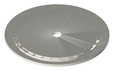
- RPM: TO-92 hall sensor (A3144 digital, SS49E analogue) in the printed mount 1–2 mm from a passing magnet; or the Ø60 slotted encoder disc through an IR slot sensor (TCST2103, 3 mm gap): 30 slots → 30 pulses/rev.
- Dial indicator stems: Ø8 mm (metric) or Ø9.53 (3/8 in, US); the clamps here hold them for measuring displacer travel and flywheel runout. Stroke of a Stirling displacer: measure at the rod with the engine turned by hand.
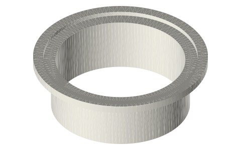
- LES: hot-end K-type under the ferrule clamp, DS18B20 on the cold spool, hall sensor at the flywheel rim, dial indicator on the displacer rod during commissioning.
Sizes
| sensor | size_mm | range | mount |
|---|---|---|---|
| DS18B20 probe | Ø6 × 50 | −55–125 °C | clamp Ø6.15 |
| K-type sheathed | Ø3 or Ø4.8 × 100 | to 1100 °C | clamp Ø3.15 / Ø4.95 |
| K-type bead | 0.3–1 mm wire | to 1000 °C | mica washer |
| hall A3144 / SS49E | TO-92 4.2 × 1.6 × 5 | — | printed mount |
| IR slot sensor TCST2103 | 3.1 mm gap | — | encoder disc Ø60 |
| dial indicator | Ø8 / Ø9.53 stem | 10 mm travel | clamp Ø8.15 / Ø9.7 |
Where the files are
Other publishers' files are linked, not hosted. "verify" = check the license at the link before commercial use.
| Wikipedia | Thermocouple | web | CC BY-SA 4.0 (text) |
| Wikipedia | Hall effect sensor | web | CC BY-SA 4.0 (text) |
| Wikipedia | Dial indicator | web | CC BY-SA 4.0 (text) |
| Analog Devices | DS18B20 datasheet | Manufacturer datasheet | |
| Long Earth Society | Engine and rig builds | web, video | LES site |
Free files
★ Free files 7 parts. Generated by Xem Studio from the standard; threads are plain cylinders at major diameter. CC BY 4.0. index.json
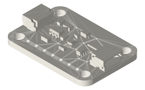
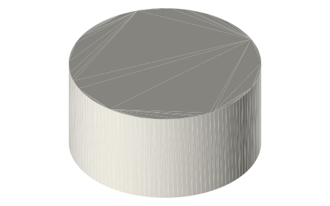
| probe-clamp-ds18b20-6mm | split clamp for a Ø6.0 probe/stem (ds18b20 6mm), M3 pinch | STEP · STL |
| probe-clamp-k-type-3mm | split clamp for a Ø3.0 probe/stem (k type 3mm), M3 pinch | STEP · STL |
| probe-clamp-k-type-4-8mm | split clamp for a Ø4.8 probe/stem (k type 4 8mm), M3 pinch | STEP · STL |
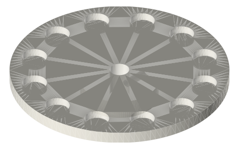
| probe-clamp-dial-indicator-8mm | split clamp for a Ø8.0 probe/stem (dial indicator 8mm), M3 pinch | STEP · STL |
| probe-clamp-dial-indicator-3-8in | split clamp for a Ø9.53 probe/stem (dial indicator 3 8in), M3 pinch | STEP · STL |
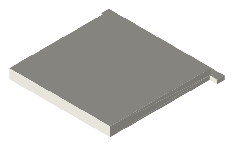
| hall-sensor-mount-to92 | TO-92 hall sensor mount (A3144 / SS49E), M3 foot | STEP · STL |
| encoder-disc-30-slots-60mm | optical encoder disc Ø60 × 1.5, 30 slots, Ø5.2 bore (for an IR slot sensor) | STEP · STL |
Plain text: sheet.txt · JSON: /api/geometry?object=instrument-mounts
Fits with
Questions
What are the dimensions of a DS18B20 waterproof probe?
Ø6 mm stainless sleeve, 50 mm long (a 30 mm version exists), with a 1 m cable; it reads to 125 °C, so it belongs on the cold side.
What diameter are K-type thermocouple probes?
Sheathed probes are Ø3 mm or Ø4.8 mm (3/16 in) by 100–150 mm; bare-bead types are just 0.3–1 mm wire and go anywhere up to 1000 °C.
How do I measure the RPM of a Stirling engine?
A hall sensor 1–2 mm from a magnet on the flywheel (one pulse per magnet), or a slotted disc through an IR slot sensor; count pulses per second × 60 / pulses per rev.