 Xem Studiomeasured geometry
Library › Stirling engines › Generators & instruments ·
Axial-flux alternator kit: magnet rotor plates, 3-phase stator, coil bobbins, hall RPM pickup
How do I build a small axial flux generator with 3D printed parts and neodymium magnets? · Hardware · basis: Classic coreless axial-flux layout: 12 magnets / 9 coils (3-phase) on Ø90, or 8 / 6 on Ø70; magnets Ø10 × 3 N42 from the library; sized to the Ø8 flywheel shaft and 608 bearings
Long Earth Society build part. The flywheel alternator on the LES generator builds. The engines · all LES parts
- sizes
- 6 in table
Notes
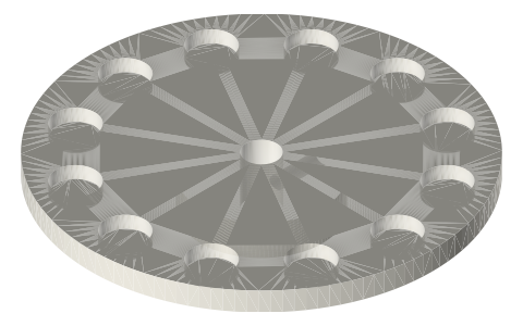
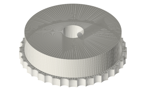
- Rotor: Ø90 plate with 12 Ø10 × 3 magnets on a 72 mm circle, poles alternating N-S around the ring; a second rotor opposite (N facing S across the gap) doubles the flux. Gap rotor-to-rotor 8 mm with a 4 mm stator between. Steel backing plates (1 mm) behind the magnets add ~40% flux.
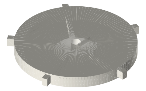
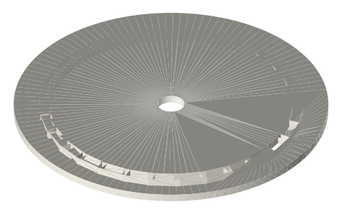
- Stator: 9 coils on the same 72 mm circle, wired 3-phase (coils 1-4-7, 2-5-8, 3-6-9 in series), rectified with a 3-phase bridge. ~150 turns of 0.3 mm enamelled wire per bobbin ≈ 1.5 Ω; at 600 rpm on the 12-pole rotor expect roughly 4–6 V open circuit per phase and a watt or two into a load: enough for the fan and LEDs, the demonstrator's purpose.
- Frequency = rpm × poles / 120 = 600 × 12 / 120 = 60 Hz. Volts scale with rpm and turns; current with wire gauge; power with magnet count and area. Hall sensor (A3144 or SS49E in the printed mount) facing a rotor magnet gives one pulse per magnet: rpm = pulses × 60 / 12.
- LES: the flywheel alternator on the generator builds; the chain/belt to a NEMA 17 used as a generator is the lazy alternative (the NEMA 17 entry covers it).
Sizes
| part | size | magnets_or_coils | shaft |
|---|---|---|---|
| rotor 90 | Ø90 × 5 + hub | 12 × Ø10×3 | Ø8 |
| rotor 70 | Ø70 × 5 + hub | 8 × Ø10×3 | Ø5 |
| stator 90 | Ø90 × 4 | 9 coils | clears Ø14 |
| stator 70 | Ø70 × 4 | 6 coils | clears Ø11 |
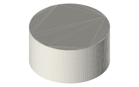
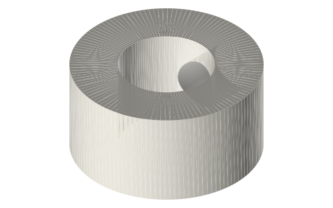
| bobbin | Ø10 × 8, Ø13 flanges | 150 t × 0.3 mm | — |
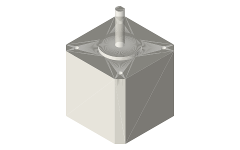
| hall mount | 14 × 10 × 20 | TO-92 | M3 |
Where the files are
Other publishers' files are linked, not hosted. "verify" = check the license at the link before commercial use.
| Wikipedia | Axial flux motor | web | CC BY-SA 4.0 (text) |
| Wikipedia | Alternator | web | CC BY-SA 4.0 (text) |
| Hugh Piggott | A Wind Turbine Recipe Book (axial-flux alternator design) | web, PDF | Author's site verify |
| Long Earth Society | Engine and rig builds | web, video | LES site |
Free files
★ Free files 6 parts. Generated by Xem Studio from the standard; threads are plain cylinders at major diameter. CC BY 4.0. index.json
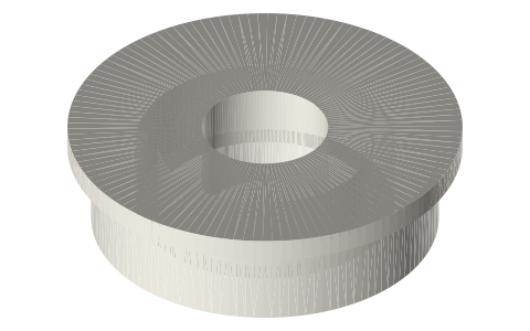
| rotor-90-12x-10x3-b8 | rotor plate Ø90 × 5: 12 pockets for Ø10 × 3 magnets (alternating poles), Ø8 bore hub with set screw (print two for a dual-rotor) | STEP · STL |
| rotor-70-8x-10x3-b5 | rotor plate Ø70: 8 magnets Ø10 × 3, Ø5 bore | STEP · STL |
| stator-90-9coil | stator plate Ø90 × 4: 9 coil pockets (3-phase, 12 pole / 9 slot), 3 mounting ears | STEP · STL |
| stator-70-6coil | stator plate Ø70: 6 coils (8 pole / 6 slot) | STEP · STL |
| coil-bobbin-10x8 | coil bobbin Ø10 core × 8 long, Ø13 flanges, wire slot; ~150 turns of 0.3 mm wire | STEP · STL |
| hall-sensor-mount-to92 | TO-92 hall sensor (A3144 / SS49E) mount: 4.2 × 1.6 slot, M3 foot; faces a rotor magnet for RPM | STEP · STL |
Plain text: sheet.txt · JSON: /api/geometry?object=axial-flux-generator-kit
Fits with
Questions
How many magnets and coils for a small axial flux generator?
12 magnets and 9 coils (3-phase) is the standard small layout; 8 and 6 for a 70 mm rotor. Poles must alternate N-S around the rotor; coils = 3/4 of poles for 3-phase.
How much power from a 90 mm axial flux generator?
With 12 Ø10×3 N42 magnets, dual rotors and 150-turn coils at 600 rpm, roughly 1–3 W; it scales with rpm², magnet area and turns. Enough to light LEDs and run a 40 mm fan from a Stirling engine.
What gap between rotor and stator?
As small as the stator thickness and wobble allow: 4 mm stator with 1.5–2 mm air gaps each side (8 mm rotor to rotor). Every mm of gap costs flux.