 Xem Studiomeasured geometry
Library › Stirling engines › Generators & instruments ·
Printer calibration coupons: hole, pin, nut-trap, T-slot tongue and bearing-pocket gauges
How do I calibrate my 3D printer so holes and shafts fit the files in this library? · Hardware · basis: Every file on this site assumes: pivot hole = pin + 0.2, press fit = pin − 0.05, bearing pocket = OD + 0.2 (OD + 0.3 above 20 mm), nut trap = AF + 0.3, T-slot tongue 5.8 in a 6 mm slot. These coupons find your printer's offset so those assumptions hold
Long Earth Society build part. Print these first; every LES part assumes these fits. The engines · all LES parts
- sizes
- 7 in table
Notes
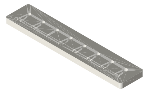
- Print the Ø3 hole gauge; push a 3 mm dowel pin through each: the first that slips freely is your 'clearance', the last that needs a tap is your 'press'. If 3.2 slips and 3.0 presses, your printer matches the library and nothing needs changing. If it takes 3.4 to slip, set a horizontal hole compensation of +0.2 mm in the slicer (or scale holes in CAD).
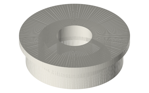
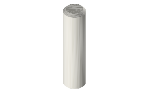
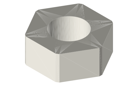
- Pin gauge: the 3.0 pin should enter a 623 bearing bore with finger pressure; if only 2.9 does, external features print fat: set XY compensation −0.05. Nut gauge: the M3 nut should push into the 5.8 AF trap and not fall out of 5.6. Tongue gauge against real 2020: 5.8 slides, 6.0 binds. Pocket gauge: a 608 presses into 22.2 with a thumb and holds.
- Do this once per printer and filament (PETG shrinks less than PLA, ABS more); write the two numbers (hole offset, XY offset) in your slicer profile. After that every STEP and STL on xemstudio.com fits as drawn, and an AI agent designing around these sheets can use the stated clearances without guessing.
Sizes
| gauge | what it tests | pass condition |
|---|---|---|
| hole 2.8–3.6 | Ø3 pivots / M3 clearance | 3.0 press, 3.2 slip, 3.4 clearance |
| hole 4.8–5.6 | Ø5 shafts | 5.0 press, 5.2 slip |
| hole 7.8–8.6 | Ø8 shafts | 8.0 press, 8.2 slip |
| pin 2.8–3.2 / 4.8–5.2 | printed pins into bearings | 3.0 / 5.0 enters finger-tight |
| nut trap M3/M4 | captive nuts | 5.8 / 7.2 AF snug |
| tongue 5.6–6.0 | T-slot brackets | 5.8 slides in 2020 |
| pocket 10/16/22 | 623 / 625 / 608 pockets | +0.2 thumb press |
Where the files are
Other publishers' files are linked, not hosted. "verify" = check the license at the link before commercial use.
| Wikipedia | Engineering tolerance | web | CC BY-SA 4.0 (text) |
| Prusa | Knowledge base: XY size compensation | web | Prusa KB verify |
| Long Earth Society | Engine and rig builds | web, video | LES site |
Free files
★ Free files 8 parts. Generated by Xem Studio from the standard; threads are plain cylinders at major diameter. CC BY 4.0. index.json
| hole-gauge-m3-2-8-to-3-6 | hole gauge for Ø3 pins/screws: 2.8–3.6 in 0.1 steps (find press, slip and clearance) | STEP · STL |
| hole-gauge-m5-4-8-to-5-6 | hole gauge for Ø5 shafts: 4.8–5.6 | STEP · STL |
| hole-gauge-m8-7-8-to-8-6 | hole gauge for Ø8 shafts: 7.8–8.6 | STEP · STL |
| pin-gauge-2-8-to-3-2 | printed pin gauge 2.8–3.2: which prints to a true Ø3 hole in a bearing? | STEP · STL |
| pin-gauge-4-8-to-5-2 | printed pin gauge 4.8–5.2 (625 bearing bore test) | STEP · STL |
| nut-trap-gauge-m3-m4 | nut-trap gauge: M3 at 5.5/5.7/5.9 AF, M4 at 7.0/7.2/7.4 | STEP · STL |
| extrusion-tongue-gauge-6mm | T-slot tongue gauge: 5.6 / 5.8 / 6.0 mm tongues for a 6 mm slot | STEP · STL |
| bearing-pocket-gauge-623-625-608 | bearing pocket gauge: Ø10.0/10.2/10.4 (623), Ø16.0/16.2/16.4 (625), Ø22.0/22.2/22.4 (608), 6 deep | STEP · STL |
Plain text: sheet.txt · JSON: /api/geometry?object=printer-calibration-coupons
Fits with
Questions
What tolerance do the files on this site assume?
Pivot holes pin + 0.2 mm, press fits pin − 0.05, bearing pockets OD + 0.2 (0.3 above 20 mm), nut traps AF + 0.3, T-slot tongues 5.8 mm. Print the gauges once to confirm your printer lands there.
My holes print too small; what do I change?
Measure which gauge hole slips over a 3 mm pin; the difference from 3.2 is your offset. Set it as hole/horizontal compensation in the slicer (+0.1 to +0.3 is typical for PLA on a 0.4 nozzle).
Why do printed holes come out undersize?
Extrusion width rounding on curves, plastic shrink and the slicer's arc approximation all push material inward; outside features come out fat by a similar amount. A one-time XY compensation fixes both.