 Xem Studiomeasured geometry
Library › Hardware › Stirling & thermoacoustic ·
Can-engine printed kit: can caps, diaphragm clamps, displacer guides, crank stands, CD/platter hubs, syringe cradles
How do I build a Stirling engine from a soda can with 3D printed parts? · Standard part · basis: Parts sized to the can, syringe, CD, platter, bearing and tube entries in this library; PLA/PETG, 0.2 mm layers, 3 perimeters
Long Earth Society build part. The printed parts for the LES can engine, sized to the cans, syringes, CDs and bearings in the library. The engines · all LES parts
- sizes
- 7 in table
Notes
- Layout (gamma, like the LES can engine): 12 oz can displacer cylinder on its side or upright over a tea light → printed can cap with a 3/32 in brass-tube guide and a 2.5 mm foam displacer rod → transfer port (Ø4.2, silicone tube) to a 10 mL syringe power piston in its cradle, or a Ø50 balloon diaphragm between two clamp rings → crank on a Ø3 skewer or Ø5 shaft in 623 bearings on the printed stands, 90° between displacer and power phase → CD flywheel on the Ø15 hub.
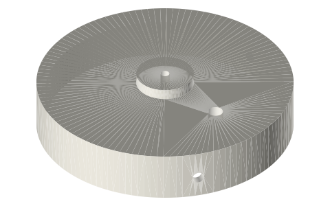
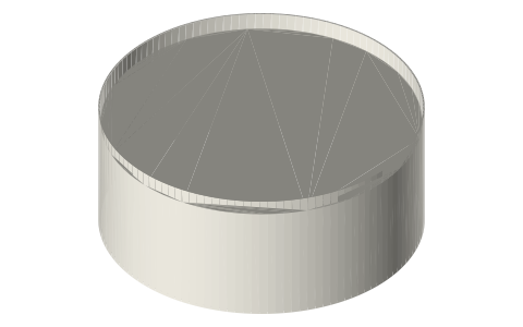
- Can cap: slides over the can body with 0.6 mm clearance, three M3 grub screws grip it; seal the joint with silicone. The guide takes 3/32 in (2.38 mm) brass tube for a 2 mm rod, or drill 3.2 for a skewer.
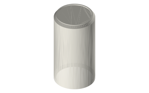
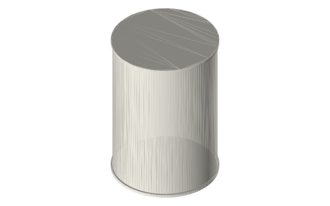
- Displacer: closed-cell foam (pool noodle, EVA) Ø62 × 30 for the 66 mm can, leaves 2 mm all round; stroke 20 mm; the can's height lets you run 110 mm of travel space. Hot end: tea light 15–20 mm under the can base.
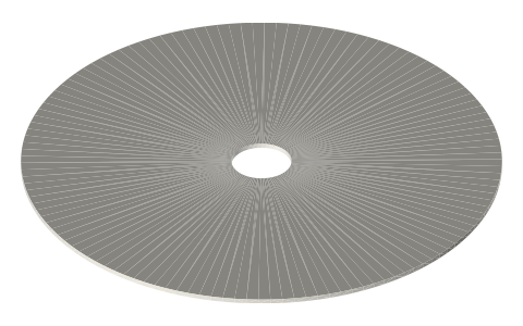
- Diaphragm: Ø50 ring pair with a Ø25 centre disc and balloon rubber, 3 mm travel; or skip it and use the syringe. Flywheel: one CD on the Ø15 hub, balanced with a coin.
- Everything on this page is on the Long Earth Society shelf: parts list and engine proportions follow the LES can-engine build.
Sizes
| part | for | fasteners | |
|---|---|---|---|
| can-cap-66 / 58 / 53.3 / 76.2 | 12 oz, sleek, slim, steel 300 cans | 3 × M3 grub | PETG, 4 perimeters |
| diaphragm-ring-40/50/60 (×2) | balloon / silicone diaphragm | 6 × M3 × 12 + nuts | any |
| diaphragm-disc | centre of the diaphragm | M3 × 10 to con-rod | any |
| crank-stand-40/60/80 (×2) | 623 bearings on a Ø3 shaft | 2 × M3 to base | PETG |
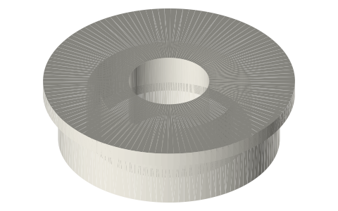
| hub-cd-15-to-5/8, hub-platter-25-to-5/8 | CD or HDD platter flywheel | M3 set screw | any |
| syringe-cradle-10/20/60ml | power piston | 4 × M3 | any |
| displacer templates | foam cutting guide | — | optional |
Where the files are
Other publishers' files are linked, not hosted. "verify" = check the license at the link before commercial use.
| Wikipedia | Stirling engine | web | CC BY-SA 4.0 (text) |
| Long Earth Society | Can engine build | video, web | LES site |
| Long Earth Society | Engine builds (videos and write-ups) | web, video | LES site |
Free files
★ Free files 23 parts. Generated by Xem Studio from the standard; threads are plain cylinders at major diameter. CC BY 4.0. index.json
| can-cap-66 | cap for a Ø66.0 can: 0.6 mm clearance, Ø2.5 displacer-rod guide (3/32 in brass tube), transfer port, 3 × M3 grub screws | STEP · STL |
| can-cap-58 | cap for a Ø58.0 can: 0.6 mm clearance, Ø2.5 displacer-rod guide (3/32 in brass tube), transfer port, 3 × M3 grub screws | STEP · STL |
| can-cap-53.3 | cap for a Ø53.3 can: 0.6 mm clearance, Ø2.5 displacer-rod guide (3/32 in brass tube), transfer port, 3 × M3 grub screws | STEP · STL |
| can-cap-76.2 | cap for a Ø76.2 can: 0.6 mm clearance, Ø2.5 displacer-rod guide (3/32 in brass tube), transfer port, 3 × M3 grub screws | STEP · STL |
| diaphragm-ring-40 | diaphragm clamp ring Ø40 bore, 6 × M3, 3 thick (print two) | STEP · STL |
| diaphragm-disc-20 | diaphragm centre disc Ø20 × 2, Ø3.2 hole for the con-rod screw | STEP · STL |
| diaphragm-ring-50 | diaphragm clamp ring Ø50 bore, 6 × M3, 3 thick (print two) | STEP · STL |
| diaphragm-disc-25 | diaphragm centre disc Ø25 × 2, Ø3.2 hole for the con-rod screw | STEP · STL |
| diaphragm-ring-60 | diaphragm clamp ring Ø60 bore, 6 × M3, 3 thick (print two) | STEP · STL |
| diaphragm-disc-30 | diaphragm centre disc Ø30 × 2, Ø3.2 hole for the con-rod screw | STEP · STL |
| crank-stand-40 | crank stand 40 mm, 623 bearing pocket (Ø10.2), 2 × M3 base holes (print two) | STEP · STL |
| crank-stand-60 | crank stand 60 mm, 623 bearing pocket (Ø10.2), 2 × M3 base holes (print two) | STEP · STL |
| crank-stand-80 | crank stand 80 mm, 623 bearing pocket (Ø10.2), 2 × M3 base holes (print two) | STEP · STL |
| hub-cd-15-to-5 | CD / DVD hub: Ø15 spigot → Ø5 shaft, M3 set screw | STEP · STL |
| hub-cd-15-to-8 | CD / DVD hub: Ø15 spigot → Ø8 shaft | STEP · STL |
| hub-platter-25-to-8 | 3.5 in HDD platter hub: Ø25 spigot → Ø8 shaft | STEP · STL |
| hub-platter-25-to-5 | 3.5 in HDD platter hub: Ø25 spigot → Ø5 shaft | STEP · STL |
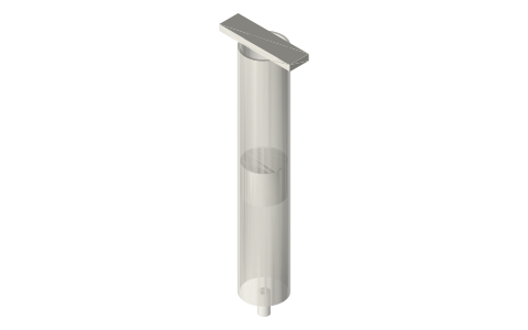
| syringe-cradle-10ml | cradle for a 10ml syringe (Ø15.9 barrel), 4 × M3 to the frame | STEP · STL |
| syringe-cradle-20ml | cradle for a 20ml syringe (Ø21.0 barrel), 4 × M3 to the frame | STEP · STL |
| syringe-cradle-60ml | cradle for a 60ml syringe (Ø29.0 barrel), 4 × M3 to the frame | STEP · STL |
| displacer-foam-62x30-template | displacer envelope for a Ø66 can: Ø62 × 30 (cut from foam or print hollow), Ø2.5 rod hole | STEP · STL |
| displacer-foam-54x25-template | displacer for a Ø58 sleek can: Ø54 × 25 | STEP · STL |
| displacer-foam-72x35-template | displacer for a Ø76 steel can: Ø72 × 35 | STEP · STL |
Plain text: sheet.txt · JSON: /api/geometry?object=can-engine-printed-kit
Fits with
Questions
What parts do I need for a soda can Stirling engine?
A 12 oz can, a tea light, foam for the displacer, a 10 mL syringe or a balloon, 3/32 in brass tube and 2 mm wire, a bamboo skewer or 5 mm shaft, two 623 bearings, a CD, M3 screws, and the printed cap, stands, hub and (optionally) diaphragm rings from this kit.
What stroke and phase does a can Stirling use?
Displacer stroke about 20 mm in a 110 mm can; power piston stroke 10–15 mm on a 10 mL syringe; crank pins 90° apart with the displacer leading.
Why does my can engine not run?
In order: leaks (silicone every joint), friction (bearings in the crank, syringe without its rubber tip), too little heat (flame 15–20 mm below the can), displacer rubbing (2 mm clearance), flywheel too light (add a second CD).