 Xem Studiomeasured geometry
Library › Stirling engines › Drives & mechanisms ·
Rhombic drive lower yoke, 25.4 mm pivot span
What are the dimensions of the piston yoke in a rhombic drive? · Hardware · basis: Yoke pivots at ±12.7 (rhombic kinematics, tools/rhombic_geom.py), pivot axes parallel to the gear shafts, rod axis across them; bore at the rod, M3 tap drill Ø2.5
Long Earth Society build part. The balanced beta drive for the 2 in tri-clamp engine; the rhombic frame head in the linkage fittings carries it on the spool. The engines
Exact dimensions. Every file is drawn at true size with no printing tolerance. The holes and pins that meet another part are listed below under Mating features, with the fit each joint needs; open those by your printer's or process's clearance before making the part. Mating features
- sizes
- 6 in table
Notes
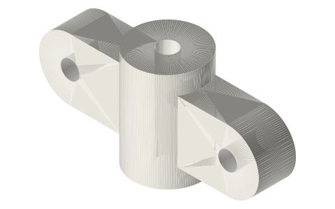
- The lower yoke of the rhombus: a 35.4 × 10 bar, 6 thick along the gear-shaft direction, with Ø3 pivot holes (fit: run) at ±12.7 running parallel to the gear shafts.
- A Ø13 × 16 boss on the rod axis (across the pivots) holds the 5 mm tube piston rod (Ø5 bore through; the Ø3 displacer rod runs on up inside it) (fit: slide), with an M3 grub (Ø2.5 tapped) entering at mid-height; an M3 × 4 grub sits flush.
- Both yokes sit in one plane on the rod axis, in front of the two link planes; the lower-yoke pivot pins are Ø3 × 16.
Sizes
| parameter | value |
|---|---|
| pivot span | 25.4 |
| bar | 35.4 × 10 × 6 |
| pivots | 2 × Ø3 (run), along the gear-shaft direction |
| boss | Ø13 × 16 |
| rod bore | Ø5 through |
| grub hole | Ø2.5 (M3) |
Mating features
Drawn at the exact size. Open press, slide, run and socket features by your process's clearance; leave designed gaps and clamp fits as drawn.
| feature | exact | mates with | fit | files |
|---|---|---|---|---|
| yoke pivots | Ø3 | Ø3 pins (turn on them) | run | yoke-* |
| yoke rod bore | Ø3 / Ø5 | displacer rod / 5 mm tube (M3 clamp) | slide | yoke-* |
| yoke clamp screw hole | Ø2.5 | M3 tap drill | designed | yoke-* |
| lower-yoke bore | Ø5 through | 5 mm tube (M3 clamp); displacer rod runs inside the tube | slide | yoke-lower-* |
Where the files are
Other publishers' files are linked, not hosted. "verify" = check the license at the link before commercial use.
| Wikipedia | Rhombic drive | web | CC BY-SA 4.0 (text) |
| Wikipedia | Stirling engine | web | CC BY-SA 4.0 (text) |
| Philips Research / Meijer | The Philips Stirling engine (rhombic drive papers, 1958–1965) | web | reference verify |
| Long Earth Society | Engine builds | web, video | LES site |
Free files
★ Free files 1 parts. Generated by Xem Studio from the standard; threads are plain cylinders at major diameter. CC BY 4.0. index.json
| yoke-lower-piston | lower yoke: as the upper, Ø13 × 16 boss with a Ø5 bore through for the 5 mm tube piston rod (M3 grub); the Ø3 displacer rod runs on up inside it | STEP · STL |
Plain text: sheet.txt · JSON: /api/geometry?object=rhombic-lower-yoke
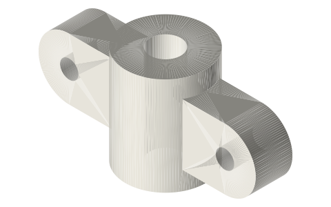
How it fits
Connects to
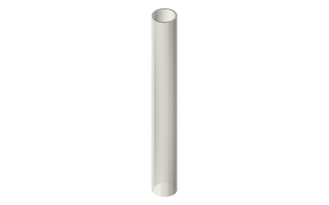 Hobby brass tube, 1/16–21/32 in and 1–12 mm,…5 mm tube piston rod in the Ø5 bore
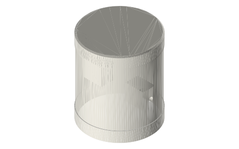 Tri-clamp power pistonthe piston at the other end of the tube rod
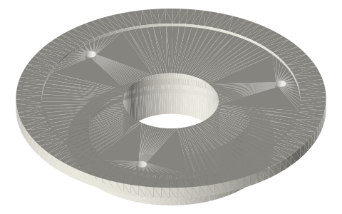 Tri-clamp flexure headpiston plug carries the tube rod
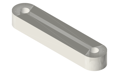 Rhombic drive link, 30 mm centrestwo links on the ±12.7 Ø3 pivots
Also needed
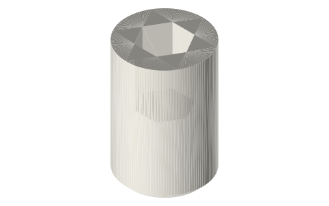 Set screws, M3–M8M3 clamp screw
In these build lists
Beta Stirling, rhombic drive, 2 in tri-clampDisplacer and piston in one bore, driven by two counter-rotating gears on a rhom…You might also need
Questions
What does the lower yoke of a rhombic drive hold?
The 5 mm tube piston rod, clamped by an M3 grub in its Ø13 boss; two links pivot on it at ±12.7.
Which way do the yoke pivot holes run?
Parallel to the gear shafts, across the rod: the links swing in planes square to the shafts.