 Xem Studiomeasured geometry
Library › Hardware › Stirling & thermoacoustic ·
Tri-clamp diaphragm centre disc and backing disc: 1.5 and 2 in
How do I attach a rod to a diaphragm membrane? · Hardware · basis: Design values: disc diameter chosen so the free membrane span gives the design stroke; M2 screws (ISO 4762) and ISO 273 medium clearance holes
Long Earth Society build part. The disc pair that carries my diaphragm rods. The engines
Exact dimensions. Every file is drawn at true size with no printing tolerance. The holes and pins that meet another part are listed below under Mating features, with the fit each joint needs; open those by your printer's or process's clearance before making the part. Mating features
- sizes
- 2 in table
Notes
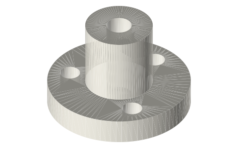
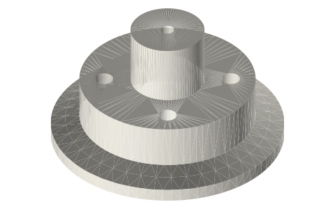
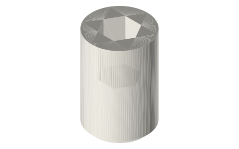
- The centre disc sits on the head side of the membrane and carries the rod: a Ø8 × 8 boss with a Ø3 socket (floor 1 mm above the membrane side) held by an M3 grub in a Ø2.5 radial hole 4 mm up the boss. The backing disc sits on the gas side.
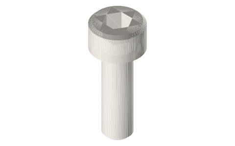
- Three M2 × 8 screws go from the gas side through the backing disc, the membrane and the centre disc into M2 nuts on top; the nuts sit flat-side to the boss.
- Disc Ø17 (1.5 in) and Ø20 (2 in): smaller discs leave more free span, so more stroke at the same membrane stretch.
Sizes
| size_in | disc_dia_mm | disc_t_mm | backing_t_mm | boss_dia_mm | boss_h_mm | screw_circle_mm | screws |
|---|---|---|---|---|---|---|---|
| 2 | 20.0 | 3.0 | 2.0 | 8.0 | 8.0 | 13.0 | 3 × M2 × 8 + nuts |
| 1.5 | 17.0 | 3.0 | 2.0 | 8.0 | 8.0 | 12.0 | 3 × M2 × 8 + nuts |
Mating features
Drawn at the exact size. Open press, slide, run and socket features by your process's clearance; leave designed gaps and clamp fits as drawn.
| feature | exact | mates with | fit | files |
|---|---|---|---|---|
| rod socket | Ø3 × 10 | Ø3 rod (M3 grub) | slide | diaphragm-disc-* |
| grub hole | Ø2.5 | M3 tap drill | designed | diaphragm-disc-* |
| screw holes | 3 × Ø2.4 | M2 clearance (ISO 273 medium) | designed | all |
Where the files are
Other publishers' files are linked, not hosted. "verify" = check the license at the link before commercial use.
| ISO | ISO 273 clearance holes for bolts and screws (fine / medium / coarse) | standard | dimensions are facts verify |
| Long Earth Society | Engine builds | web, video | LES site |
Free files
★ Free files 4 parts. Generated by Xem Studio from the standard; threads are plain cylinders at major diameter. CC BY 4.0. index.json
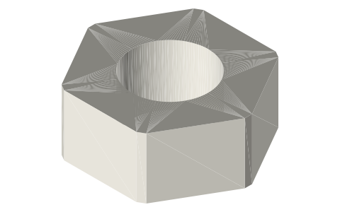
| diaphragm-disc-2in | 2 in centre disc Ø20 × 3, rod boss Ø8 × 8 with Ø3 socket and Ø2.5 grub hole (M3 tap drill), 3 × Ø2.4 on Ø13 | STEP · STL |
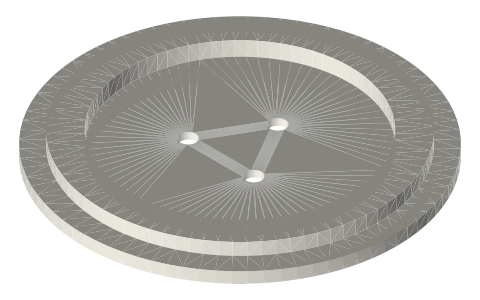
| diaphragm-backing-2in | 2 in backing disc Ø20 × 2, 3 × Ø2.4 on Ø13 (gas side of the membrane) | STEP · STL |
| diaphragm-disc-1.5in | 1.5 in centre disc Ø17 × 3, rod boss Ø8 × 8 with Ø3 socket and Ø2.5 grub hole (M3 tap drill), 3 × Ø2.4 on Ø12 | STEP · STL |
| diaphragm-backing-1.5in | 1.5 in backing disc Ø17 × 2, 3 × Ø2.4 on Ø12 (gas side of the membrane) | STEP · STL |
Plain text: sheet.txt · JSON: /api/geometry?object=tri-clamp-diaphragm-disc
How it fits
In these build lists
Tri-clamp tee diaphragm gamma, 2 inA tea-light gamma in 2 in tri-clamp: displacer in a 3 in spool, a short-outlet t…Tri-clamp elbow diaphragm alpha, 2 inA torch-heated alpha in 2 in tri-clamp: a square of fittings with a diaphragm he…You might also need
Questions
How is the rod held?
In the Ø3 socket of the centre-disc boss by an M3 grub screw.
Which side does each disc go?
Centre disc (with the boss) on the head side, backing disc on the gas side; the screw heads are on the gas side.