 Xem Studiomeasured geometry
Library › Hardware › Stirling & thermoacoustic ·
Tri-clamp flexure leaf: spiral planar spring clamped in a 2 in joint like a gasket (displacer and piston)
Can a flexure bearing be clamped in a tri-clamp joint? · Hardware · basis: Leaf stiffness and stress from a 3D Euler-Bernoulli frame model of the spiral arms (rim clamped at the bore, hub rigid), modulus 200 GPa assumed
Used in Long Earth Society builds. Designing a displacer for a 3-foot free-piston Stirling engine · Designing a free-piston Stirling engine · Laser-cut linear flexure bearing
Exact dimensions. Every file is drawn at true size with no printing tolerance. The holes and pins that meet another part are listed below under Mating features, with the fit each joint needs; open those by your printer's or process's clearance before making the part. Mating features
- sizes
- 2 in table
Notes
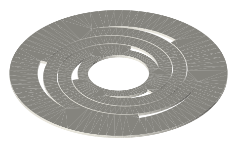
- Each leaf is a flat disc the size of the gasket web (Ø64) with three spiral arms inside the bore. It sits in a tri-clamp joint between two half gaskets whose webs add up, with the leaf, to the Type B gasket's 1.7: the clamp closes on it exactly as on a gasket, and it centres on the Ø64 flange rims.
- Displacer leaf (joint B, 0.5 thick, 3 arms × 3 wide, 400°): axial 730 N/m, radial 40 kN/m, bending stress 14.3 MPa per mm of travel (86 MPa at ±6).
- Piston leaves (joints C and D, 0.8 thick, 3 × 4 wide, 330°, the second turned over for the opposite hand): axial 3949 N/m each, radial 154 kN/m each, 23.3 MPa per mm (117 MPa at the ±5 design stroke, 140 MPa at ±6).
- The two piston leaves hold the piston against the stator's magnetic side pull: about 55 kN/m of negative radial stiffness (estimate) against 308 kN/m from the leaves (5.6 ×).
- The leaf must not fatigue at the stress above for 10⁹ cycles and more: the leaf's material and finish are the builder's choice and the builder's check.
Sizes
| leaf | t_mm | arm_w_mm | sweep_deg | hub_bore_mm | k_axial_N_m | k_radial_kN_m | MPa_per_mm |
|---|---|---|---|---|---|---|---|
| displacer | 0.5 | 3.0 | 400 | 12.0 | 730 | 40.0 | 14.3 |
| piston | 0.8 | 4.0 | 330 | 18 | 3949 | 154.1 | 23.3 |
Mating features
Drawn at the exact size. Open press, slide, run and socket features by your process's clearance; leave designed gaps and clamp fits as drawn.
| feature | exact | mates with | fit | files |
|---|---|---|---|---|
| rim | Ø64 × 0.5 / 0.8, clamped from Ø47.5 out | two half gaskets in the joint; centred on the Ø64 flange rims by the clamp | clamp | all |
| hub bore | Ø12 (displacer) / Ø18 (piston) | rod / tube rod, hub clamped by collars | slide | all |
| arms | three spiral arms inside Ø47.5 | free (no contact) | designed | all |
Where the files are
Other publishers' files are linked, not hosted. "verify" = check the license at the link before commercial use.
| NASA (NTRS, public domain) | Wong, Wood & Wilson (2008), Advanced Stirling Convertor (ASC): 88 We, 850 °C hot end, 38 % efficiency, 1.3 kg | US Government work, public domain | |
| Long Earth Society | Engine builds | web, video | LES site |
Free files
★ Free files 2 parts. Generated by Xem Studio from the standard; threads are plain cylinders at major diameter. CC BY 4.0. index.json
| leaf-2in-displacer-t0.5 | displacer leaf: Ø64 × 0.5 rim (clamped from Ø47.5 out), hub Ø18 with Ø12 bore, 3 arms 3 wide sweeping 400° from r 9 to r 23.75 | STEP · STL |
| leaf-2in-piston-t0.8 | piston leaf: Ø64 × 0.8 rim (clamped from Ø47.5 out), hub Ø24 with Ø18 bore, 3 arms 4 wide sweeping 330° from r 12 to r 23.75 | STEP · STL |
Plain text: sheet.txt · JSON: /api/geometry?object=tri-clamp-flexure-leaf
How it fits
In these build lists
Free-piston Stirling generator, 2 in tri-clamp…A real free-piston Stirling generator in standard 2 in sanitary fittings: closed…You might also need
Questions
Why clamp the leaf in the joint?
The joint is already the most accurate datum in the vessel: the clamp centres both flanges and the leaf on the same Ø64, and the gaskets seal over it. No bracket, no screws, no extra seal.
Does the leaf add dead volume?
Almost none: it is 0.5 or 0.8 thick and its arms move in the clearance the piston and displacer need anyway.