 Xem Studiomeasured geometry
Library › Hardware › Stirling & thermoacoustic ·
Link webs: a second crank throw on the first crank pin
How do I put two crank pins at different angles on one overhung crank? · Hardware · basis: Design values (pin radii and angles set by the engines' kinematics); Ø3 dowel pins (ISO 8734)
Long Earth Society build part. The second throw on my rolling-diaphragm beta and gamma. The engines
Exact dimensions. Every file is drawn at true size with no printing tolerance. The holes and pins that meet another part are listed below under Mating features, with the fit each joint needs; open those by your printer's or process's clearance before making the part. Mating features
- sizes
- 2 in table
Notes
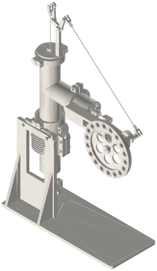
- The web is pressed on crank pin 1 (which is pressed in the crank disc) and carries crank pin 2. The power con-rod runs on pin 1 between the disc and the web; the displacer drive runs on pin 2 outside the web. The shaft ends at the disc, so nothing crosses the con-rods' path.
- Beta web: pin 2 at the same 10 mm radius, 90° from pin 1. Gamma web: pin 2 at 7 mm, 45° from pin 1; with the bell crank's own lag the displacer leads the power piston's volume by close to a quarter turn.
- Turn the web over to swap which way pin 2 leads: the web is the same both ways.
Sizes
| part | pin1_radius_mm | pin2_radius_mm | angle_deg | thickness_mm |
|---|---|---|---|---|
| rd-link-web-r10-90 | 10.0 | 10.0 | 90.0 | 14.0 |
| rd-link-web-r7-45 | 10.0 | 7.0 | 45.0 | 14.0 |
Mating features
Drawn at the exact size. Open press, slide, run and socket features by your process's clearance; leave designed gaps and clamp fits as drawn.
| feature | exact | mates with | fit | files |
|---|---|---|---|---|
| pin holes | Ø3 (two) | Ø3 crank pins (dowels) | press | all |
Where the files are
Other publishers' files are linked, not hosted. "verify" = check the license at the link before commercial use.
| Long Earth Society | Engine builds | web, video | LES site |
Free files
★ Free files 2 parts. Generated by Xem Studio from the standard; threads are plain cylinders at major diameter. CC BY 4.0. index.json
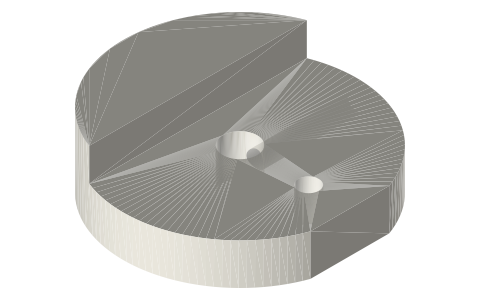
| rd-link-web-r10-90 | link web 14 thick: Ø3 press holes for crank pin 1 (radius 10) and pin 2 (radius 10) 90° apart about the shaft axis, Ø12 ends | STEP · STL |
| rd-link-web-r7-45 | link web 14 thick: Ø3 press holes for crank pin 1 (radius 10) and pin 2 (radius 7) 45° apart about the shaft axis, Ø12 ends | STEP · STL |
Plain text: sheet.txt · JSON: /api/geometry?object=tri-clamp-rd-link-webs
How it fits
In these build lists
Tri-clamp rolling-diaphragm beta, 2 inA torch-heated beta in two pieces of pressure vessel: a 2 in × 150 cup with the …Tri-clamp rolling-diaphragm gamma, 2 inThe Ringbom's cup, tee and power head with the displacer on the crank: a pushrod…You might also need
Questions
Which way does the engine turn?
The way that makes the displacer lead the power piston; turning the web over reverses it.