 Xem Studiomeasured geometry
Tri-clamp rolling-diaphragm gamma, 2 in
The Ringbom's cup, tee and power head with the displacer on the crank: a pushrod from a second crank pin to a bell crank on the gland cap.
Numbers (with the optional finned cooler; cold end taken at 320 K): power swept 20.0 mL, displacer swept 30.4 mL, dead volume 57 mL (swept/dead 0.35); Schmidt work at 650 / 320 K and 1 bar mean 0.33 J per turn (1.39 pressure ratio, ±16 kPa); shaft power about 0.4–1.7 W at 300–600 rpm (0.25–0.5 of Schmidt).
Exact dimensions. Every part is drawn at true size with no printing tolerance; each part's page lists its mating features and the fit each joint needs, so open those by your process's clearance before making the parts.
55 parts, every one a file here · all STL URLs · Markdown · tick lines as you go (saved in this browser)
| subsystem | object | parts | qty | note | |
|---|---|---|---|---|---|
| None | Frame for the rolling-diaphragm tri-clam | rd-frame-2in STEP · STL | 1 | base, wall, gussets | |
| None | Torch stand for a horizontal tri-clamp h | torch-stand-40 STEP · STL | 1 | on the base, post toward +Y; the heat source is a torch flame 40 mm under the cup | |
| None | Socket head cap screws | shcs-m4x10 STEP · STL | 2 | torch stand to the base | |
| None | Set screws (grub screws) | set-m4x10 STEP · STL | 3 | centre the torch head in the stand ring | |
| None | Tri-clamp cups | cup-2in-150 STEP · STL | 1 | the hot end and displacer cylinder in one piece: no joint near the flame | |
| None | Spool hanger collars | hanger-2in-tab STEP · STL | 1 | on the cup under the top clamp; bar to the wall | |
| None | Spool hanger collars | hanger-2in-plain STEP · STL | 1 | closes the hanger | |
| None | Socket head cap screws | shcs-m5x25 STEP · STL | 2 | hanger bar through the wall | |
| None | Socket head cap screws | shcs-m4x20 STEP · STL | 2 | hanger ears | |
| None | Hex nuts | nut-m4 STEP · STL | 2 | hanger ears | |
| None | Tri-clamp finned cooler | cooler-half-2in-56 STEP · STL | 2 | optional: clamp-on fin halves on the cup under the hanger (the cold end of the displacer cylinder); without them the engine runs with less power, or cool that part of the cup any way you like | |
| None | Socket head cap screws | shcs-m4x30 STEP · STL | 4 | optional: cooler ears (only with the cooler) | |
| None | Hex nuts | nut-m4 STEP · STL | 4 | optional: cooler ears (only with the cooler) | |
| None | Top-hat rolling diaphragm | rd-diaphragm-1.50-h1.50 STEP · STL | 1 | 1.50 in bore, 1.50 in high, flat flange: clamped in the joint in place of a gasket | |
| None | Tri-clamp rolling-diaphragm power head | rd-power-head-2in STEP · STL | 1 | standard 2 in clamp face, Ø38.10 cylinder, bushing seat, crank tower | |
| None | Tri-clamp rolling-diaphragm power head | rd-seat-ring-2in STEP · STL | 1 | in the head's face recess, behind the diaphragm flange | |
| None | Tri-clamp clamp | clamp-half-2in STEP · STL | 6 | 3 joints, two halves each | |
| None | Socket head cap screws | shcs-m5x30 STEP · STL | 6 | clamp bolts | |
| None | Hex nuts | nut-m5 STEP · STL | 8 | clamp nuts (6), hanger bar (2) | |
| None | Plain sleeve bushings Ø3 to Ø10 ID | bushing-5x8x12 STEP · STL | 2 | back to back in the head's Ø8 seat: guide the tube rod | |
| None | Rolling-diaphragm piston and head retain | rd-piston-2in STEP · STL | 1 | Ø33.27, never touches the bore | |
| None | Rolling-diaphragm piston and head retain | rd-retainer-26-blind STEP · STL | 1 | clamps the diaphragm head on the crown | |
| None | Button head socket screws | button-m3x8 STEP · STL | 3 | retainer screws into the crown | |
| None | Tube piston rods Ø5 × Ø3.4 | tube-rod-5x3.4x80 STEP · STL | 1 | piston to yoke, through the bushings | |
| None | Rod-end yokes with a side stub pin | rd-yoke-tube5 STEP · STL | 1 | on the tube rod's end | |
| None | Set screws (grub screws) | set-m3x3 STEP · STL | 1 | tube yoke grub | |
| None | Connecting rods 30 to 80 mm centres with | conrod-80 STEP · STL | 1 | power | |
| None | Counterweighted crank discs | cw-crank-disc-stroke20 STEP · STL | 1 | 20 mm stroke, overhung on the shaft end | |
| None | Crankshafts Ø3 | crankshaft-5x80-dflat STEP · STL | 1 | disc face to flywheel hub | |
| None | Shaft spacers for Ø3 | spacer-5mm-t5 STEP · STL | 1 | disc hub to the front bearing | |
| None | Shaft spacers for Ø3 | spacer-5mm-t1 STEP · STL | 1 | ||
| None | Ball bearings | bearing-625 STEP · STL | 2 | in the tower | |
| None | Set-screw shaft collars Ø3 to Ø12 | collar-5mm STEP · STL | 1 | behind the tower | |
| None | Flywheels Ø100–Ø200 with hex-nut rim poc | flywheel-150-m10-b5 STEP · STL | 1 | on the shaft's far end | |
| None | Hex nuts M8 | nut-m10 STEP · STL | 18 | one in each rim pocket | |
| None | Sanitary clamp tees and short-outlet tee | tee-2in STEP · STL | 1 | standard 2 in equal tee: run upright on the cup, branch toward +X for the power head | |
| None | Tri-clamp gasket | tc-gasket-2in STEP · STL | 2 | Type B: cup to tee, tee to gland cap | |
| None | Tee inserts | rd-tee-insert-2in-gamma STEP · STL | 1 | fills the tee's run between the two gasket lips | |
| None | Tee inserts | rd-branch-insert-2in STEP · STL | 1 | fills the tee's branch; its spigot locates the run insert | |
| None | Tri-clamp gland caps | rd-gland-cap-2in-gamma STEP · STL | 1 | closes the top of the tee's run, carries the rod's gland | |
| None | Set screws (grub screws) | set-m5x6 STEP · STL | 1 | plug in the gland cap's M5 port (or a gauge or one-way valve) | |
| None | Plain sleeve bushings Ø3 to Ø10 ID | bushing-3x5x6 STEP · STL | 2 | the displacer rod's gland, one at each end of the gland cap's boss | |
| None | Tri-clamp displacer | displacer-shell-2in-120 STEP · STL | 1 | Ø46 × 120, 0.75 radial gap, 18.3 stroke | |
| None | Tri-clamp displacer | displacer-cap-2in STEP · STL | 1 | closes the shell, holds the rod | |
| None | Displacer rods Ø2 × 60 | rod-3x350 STEP · STL | 1 | displacer rod: up through the tee insert and the gland | |
| None | Displacer rods Ø2 × 60 | rod-3x300 STEP · STL | 1 | pushrod: crank pin 2 to the bell crank | |
| None | Rod clevises for a Ø2 or Ø3 rod or a Ø5 | rod-clevis-3mm STEP · STL | 3 | displacer rod top, both pushrod ends | |
| None | Link webs | rd-link-web-r7-45 STEP · STL | 1 | on crank pin 1, carries pin 2 | |
| None | Bell cranks | bell-crank-30x30-90 STEP · STL | 1 | on the gland cap's post: arm A up to the pushrod, arm B over the displacer rod | |
| None | Connecting rods 30 to 80 mm centres with | conrod-40 STEP · STL | 1 | bell crank arm B to the displacer rod's clevis | |
| None | Ball bearings | bearing-623 STEP · STL | 5 | con-rod eyes (4), bell-crank pivot (1) | |
| None | Dowel pins | dowel-3x12 STEP · STL | 2 | tube-yoke stub pin, bell-crank arm B | |
| None | Dowel pins | dowel-3x16 STEP · STL | 1 | bell-crank pivot in the post | |
| None | Dowel pins | dowel-3x20 STEP · STL | 4 | crank pin 1; crank pin 2 through the pushrod clevis; arm A through the pushrod clevis; displacer clevis pin with the con-rod beside it | |
| None | Set screws (grub screws) | set-m3x4 STEP · STL | 8 | grubs: displacer cap, 3 clevises, piston, crank disc, collar, flywheel |
Assembled engine
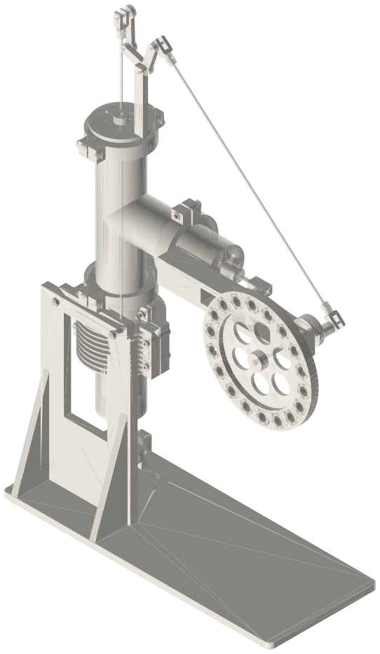
A torch-heated 2 in tri-clamp gamma Stirling engine with a rolling-diaphragm power piston: a 150 mm cup with the displacer, a standard 2 in tee on it with a gland cap on top and the power head on its branch, a pushrod from a second crank pin to a bell crank that lifts the displacer rod, and a Ø150 flywheel, hung on a wall frame over a torch stand; about 423 × 150 × 570 mm.
Assembly STEP (3.3 MB) · STL (9.9 MB) · 125 parts
Build order
- Frame, torch stand, cup with its hanger (and the optional cooler) as on the Ringbom.
- Displacer: shell, cap, Ø3 × 350 rod (grub); into the cup. Type B gasket, tee, clamp; run insert and branch insert as on the Ringbom. Type B gasket, gamma gland cap (two 3 × 5 × 6 bushings pressed in), clamp. Rod clevis on the rod top.
- Power head as on the Ringbom, with the link web and pin 2 on the crank.
- Bell crank on the post (623 on the Ø3 × 16 pin); conrod-40 from arm B to the rod clevis (Ø3 × 20 through the clevis, con-rod beside it); pushrod clevises on arm A and on pin 2.
Agents: each row's object has /api/geometry?object=slug and the MCP tool get_free_files; the STL list above is every part.