 Xem Studiomeasured geometry
Library › Hardware › Stirling & thermoacoustic ·
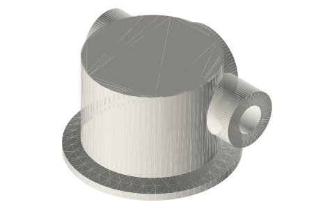
2 in end cap with a 1/2 NPT transfer boss, two 1/4 NPT bosses and a spigot (transfer cap)
How do I join two tri-clamp cylinders with a short gas passage? · Hardware · basis: ISO 2852 2 in face as on this site; 1/2 and 1/4 NPT per ASME B1.20.1; passages and spigot are design values
Long Earth Society build part. The transfer caps of my horizontal gamma. The engines
Exact dimensions. Every file is drawn at true size with no printing tolerance. The holes and pins that meet another part are listed below under Mating features, with the fit each joint needs; open those by your printer's or process's clearance before making the part. Mating features
- sizes
- 5 in table
Notes
- A fabrication spec: a solid 2 in end cap with a 1/2 NPT boss on its side, two 1/4 NPT bosses and a spigot that fills the joint's dead space. Two of them, on two cylinders 120 mm apart with their transfer bosses facing, join with two 1/2 NPT × 1/2 in tube fittings and a 64 mm length of 1/2 in tube: the gamma's transfer passage.
- Gas path: spigot face → Ø11 axial passage (off-centre) → the 1/2 NPT port → fitting → tube (bore 10.9). Volume of the whole transfer path about 22.2 mL; its friction is in the engine's numbers.
- The rod-gland version carries the displacer rod in two 6 × 10 × 10 sleeve bushings 46 mm apart. The NPT bosses take the working space's fill valve, gauge, relief valve and a plug.
Sizes
| feature | value |
|---|---|
| face | ISO 2852 2 in |
| spigot | Ø44.0 to 3.15 past the face |
| transfer boss | 1/2 NPT, Ø30, face 28 from the axis, z 24 |
| NPT | 2 × 1/4 at z 24, y 13, ±X |
| gland | Ø10 seat z 30–86 (rod version) |
Mating features
Drawn at the exact size. Open press, slide, run and socket features by your process's clearance; leave designed gaps and clamp fits as drawn.
| feature | exact | mates with | fit | files |
|---|---|---|---|---|
| face | ISO 2852 2 in | Type B gasket, 2 in clamp | clamp | all |
| spigot | Ø44.0 to 3.15 past the face | inside the gasket lip Ø45.3 (no contact) | designed | all |
| transfer boss | 1/2-14 NPT, tap drill Ø18.3 × 14 | 1/2 NPT × 1/2 in tube fitting | designed | all |
| port bosses | 2 × 1/4-18 NPT, tap drill Ø11.1 × 12 | gauge, relief valve, fill valve, plug | designed | all |
| gland seat | Ø10, z 30–86 | two 6 × 10 × 10 sleeve bushings | press | transfer-cap-2in-rod6* |
Where the files are
Other publishers' files are linked, not hosted. "verify" = check the license at the link before commercial use.
| ISO (via iTeh sample) | ISO 2852 clamp liners: face profile and flange / groove diameters | standard excerpt; dimensions are facts | |
| ASME | BPE Bioprocessing Equipment (clamp fitting dimensions, tube OD and wall) | standard | ASME; dimensions are facts verify |
| ASME | ASME B1.20.1 Pipe Threads, General Purpose, Inch (NPT): 1/4-18 major Ø13.72, tap drill 7/16 in (11.1), L2 10.2 | standard | ASME; dimensions are facts verify |
| Long Earth Society | Engine builds | web, video | LES site |
Free files
★ Free files 2 parts. Generated by Xem Studio from the standard; threads are plain cylinders at major diameter. CC BY 4.0. index.json
| transfer-cap-2in-rod6 | 2 in transfer cap with rod gland: ISO 2852 face, body Ø50.8 × 40, spigot Ø44 to 3.15 past the face, Ø11 axial passage at y 13, 1/2 NPT transfer boss (+Y, face 28 from the axis, z 24), two 1/4 NPT bosses (±X, z 24), Ø10 seat z 30–86 for two 6 × 10 × 10 bushings | STEP · STL |
| transfer-cap-2in-blind | 2 in transfer cap, blind: as the rod-gland cap without the gland boss | STEP · STL |
Plain text: sheet.txt · JSON: /api/geometry?object=tri-clamp-transfer-cap
How it fits
In these build lists
Tri-clamp horizontal gamma generator, 2 in,…The classic desk Stirling generator in tri-clamp, built for power: a horizontal …You might also need
Questions
Why a spigot?
Without it the joint between the cap and the cylinder is a few mL of gas that does no work; the spigot fills it to within 0.5 mm of the liner.