 Xem Studiomeasured geometry
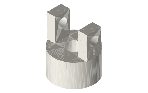
Universal joint for Ø5 shafts: Ø14 yokes and 8 mm cross spider
How is a small universal joint for 5 mm shafts built? · Hardware · basis: Cardan joint: two yokes on Ø3 cross pins through an 8 × 8 spider; yoke arm gap equals the spider span
Long Earth Society build part. Serviceable pivots on the LES linkages; a U-joint between engine and alternator when the shafts don't line up. The engines
Exact dimensions. Every file is drawn at true size with no printing tolerance. The holes and pins that meet another part are listed below under Mating features, with the fit each joint needs; open those by your printer's or process's clearance before making the part. Mating features
- sizes
- 2 in table
Notes
- Two identical yokes (one file, make two) and one spider. Yoke: Ø14 × 8 hub with a Ø5 bore and a radial Ø2.5 (M3 tap drill) hole 4 mm up, two arms 3 thick × 5 wide rising to 16 overall, 8 mm apart, with a Ø3 cross hole 13 mm from the base.
- Spider: an 8 × 8 × 5 cross of 5 × 5 arms. One Ø3 hole runs straight through on one axis; the other axis has two Ø3 blind holes 2.5 deep, so two short pins stop clear of the through pin.
- The spider's 8 mm span fills the yokes' 8 mm arm gap. A single joint passes rotation through an angle with a once-per-half-turn speed ripple; two joints with their inner yokes in line cancel it.
Sizes
| part | envelope | bore | cross holes | arm gap / span |
|---|---|---|---|---|
| ujoint-yoke-5mm | Ø14 × 16 | Ø5 + M3 tap Ø2.5 | Ø3 at 13 from base | 8 |
| ujoint-spider-14 | 8 × 8 × 5 | — | Ø3 through + 2 × Ø3 × 2.5 blind | 8 |
Mating features
Drawn at the exact size. Open press, slide, run and socket features by your process's clearance; leave designed gaps and clamp fits as drawn.
| feature | exact | mates with | fit | files |
|---|---|---|---|---|
| yoke bore | Ø5 | Ø5 shaft (M3 set screw) | slide | ujoint-yoke-* |
| set-screw hole | Ø2.5 | M3 tap drill | designed | ujoint-yoke-* |
| cross-pin holes | Ø3 | Ø3 pin (turns in it) | run | ujoint-yoke-* |
| arm gap | 8 | spider arm span 8 | run | ujoint-yoke-* |
| pin holes | Ø3 through + two Ø3 × 2.5 blind | one through pin, two short pins | press | ujoint-spider-* |
| arm span | 8 | yoke arm gap 8 | run | ujoint-spider-* |
Where the files are
Other publishers' files are linked, not hosted. "verify" = check the license at the link before commercial use.
| Wikipedia | Clevis fastener | web | CC BY-SA 4.0 (text) |
| Wikipedia | Universal joint | web | CC BY-SA 4.0 (text) |
| Wikipedia | Rod end bearing | web | CC BY-SA 4.0 (text) |
| McMaster-Carr | Clevis pins (free STEP per part, for your own design use; no redistribution) | STEP, PDF | McMaster-Carr site terms verify |
| McMaster-Carr | Rod ends (free STEP per part, for your own design use; no redistribution) | STEP, PDF | McMaster-Carr site terms verify |
| Long Earth Society | Engine and rig builds | web, video | LES site |
Free files
★ Free files 2 parts. Generated by Xem Studio from the standard; threads are plain cylinders at major diameter. CC BY 4.0. index.json
| ujoint-yoke-5mm | universal joint yoke Ø14, Ø5 bore, M3 set screw (Ø2.5 tap drill), Ø3 cross-pin holes, 8 mm between the arms | STEP · STL |
| ujoint-spider-14 | universal joint spider for the Ø14 yokes: 8 × 8 cross of 5 × 5 arms; Ø3 through hole for one pin, and two Ø3 blind holes 2.5 deep at 90° for short pins that stop clear of it | STEP · STL |
Plain text: sheet.txt · JSON: /api/geometry?object=universal-joint-5mm
How it fits
Goes in or on
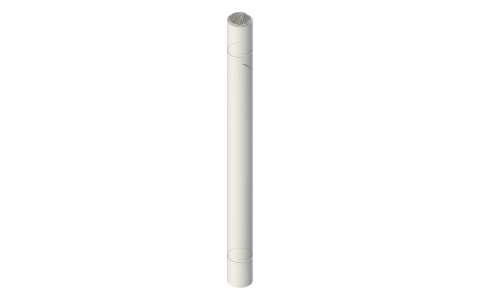 Metric shafts Ø3 to Ø10 with D-flats and clip…Ø5 shaft in the yoke bore
Alternatives
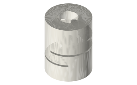 Flexible shaft couplers, 5–10 mm boresin-line shafts
Also needed
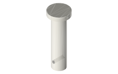
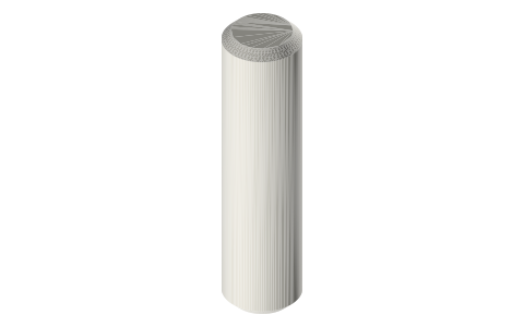 Dowel pins, 2–6 mmØ3 cross pins
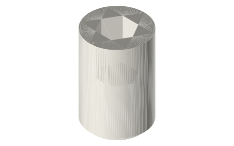 Set screws, M3–M8M3 grub in the yoke
You might also need
Questions
What size is the universal joint?
Yokes Ø14 × 16 tall on Ø5 shafts, spider 8 × 8 × 5, Ø3 cross pins; assembled it spans two yokes plus the spider.
Why does the spider have blind holes?
One Ø3 pin goes straight through on one axis; the crossing axis takes two short pins in 2.5 mm blind holes so they stop clear of it.