 Xem Studiomeasured geometry
Library › Hardware › Mechanism parts ·
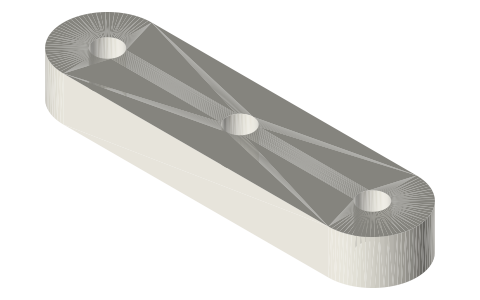
Cartwright crosshead bar, 30 mm pin spacing, centre rod hole
What is the crosshead in Cartwright's parallel motion? · Modern device · basis: Xem Studio design following Brown's figure (1868); true size, no printing allowance
Also called: crosshead bar, cruceta, Kreuzkopfsteg
Exact dimensions. True size, with no printing tolerance added.
- length
- 40.0 mm
- width
- 10.0 mm
- height
- 5.0 mm
Notes
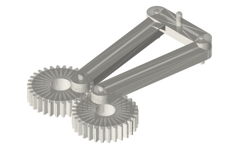
- 40 × 10 × 5 bar with Ø3 holes at −15, 0 and +15 mm: the two connecting rods pin to the outer holes, the guided rod to the centre one, which moves on a straight line.
- Xem Studio design following Brown's figure; true size, no printing allowance (apply your own to the mating features).
Cartwright crosshead bar, 30 mm pin spacing, centre rod hole size chart
| dimension | value |
|---|---|
| pin spacing | 30 mm |
| holes | 3 × Ø3 |
| bar | 40 × 10 × 5 mm |
Where the files are
Other publishers' files are linked, not hosted. "verify" = check the license at the link before commercial use.
| Henry T. Brown (1868, public domain) | Five Hundred and Seven Mechanical Movements — scan on archive.org | web | Publisher's page; dimensions are facts |
| 507movements.com | Brown's movement No. 328: figure, his text and an animation | web | Publisher's page; dimensions are facts |
| Xem Studio | drawing | web | Publisher's page; dimensions are facts |
Free files
★ Free files 1 parts. Generated by Xem Studio from the standard; threads are plain cylinders at major diameter. CC BY 4.0. index.json
https://xemstudio.com/mcp to Claude, ChatGPT, Cursor or any MCP client (free, no account, one minute) and it can look up exact sizes, mating fits and free STEP/STL from every chat.Plain text: sheet.txt · JSON: /api/geometry?object=cartwright-crosshead-30
Fits with
Questions
What is the crosshead in Cartwright's parallel motion?
40 × 10 × 5 bar with Ø3 holes at −15, 0 and +15 mm: the two connecting rods pin to the outer holes, the guided rod to the centre one, which moves on a straight line.