 Xem Studiomeasured geometry
Library › Mechanisms › Gears ·
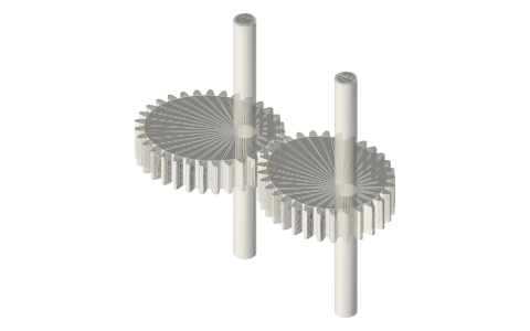
Elliptical gears turning about their foci (speed ratio 0.33 – 3)
How do elliptical gears give a varying speed? · Hardware · basis: Xem Studio design following Brown No. 33 (1868)
Also called: elliptical gears, oval gears, non-circular gears, variable speed gears, engranajes elípticos, elliptische Zahnräder
Exact dimensions. True size, with no printing tolerance added.
- sizes
- 4 in table
Notes
- Resize: multiply every length by one factor k and the motion stays identical: angles, ratios, timing and the formulas below do not change, because a mechanism's motion depends only on the ratios of its lengths. Here, scales with k: pivots; stays the same: gears, ratio range, pose.
- Resize: Gears scale by the module m (pitch Ø = m·z, centre distance = m·(z₁ + z₂)/2): keep the tooth counts so the ratio stays, and choose a standard module (0.5, 0.8, 1, 1.25, 1.5, 2, 2.5, 3).
- Resize: fit clearances stay in mm (a slide fit is the same gap at any size); keep every printed wall and pin at least two nozzle widths; mass grows with k³ but part strength only with k², so at k = 2 parts are about 8× heavier and 4× stronger: check pins and thin links when scaling up.
- Two equal ellipses pivoted at one focus each, the pivots one major axis apart, roll on each other without slipping: the contact is always on the line of centres and the two focal radii there always add up to the major axis, so the pair stays in mesh while the speed ratio swings.
- Ratio = r₂/r₁ at the contact, from (1 − e)/(1 + e) = 0.33 to (1 + e)/(1 − e) = 3 once per turn (e = 0.5): a uniform input gives a fast–slow output, as in quick-return drives and printing presses. Brown notes the variation depends on the ratio of the axes.
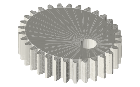
- Here two identical module 1.5, 31-tooth gears, pitch ellipse 49.77 × 43.11 mm, pivots 49.77 mm apart, drawn with the driver turned 35°. The outlines were checked against each other at 72 angles through a turn (largest 2D overlap 0.0000 mm²) and in 3D at seven poses. Brown's No. 33.
- Parts (each has its own page): elliptical-gear-m1-5-31t-e0-5-focus-bore, linear-shafts-h6.
- Brown's movement No. 33 (1868) shows it; this model is a Xem Studio design following his figure, every part at true size.
Elliptical gears turning about their foci size chart
| parameter | value |
|---|---|
| gears | 2 × module 1.5, 31 T, e = 0.5 |
| pivots | foci, 49.77 mm apart |
| ratio range | 0.33 – 3 |
| pose | driver at 35° |
Where the files are
Other publishers' files are linked, not hosted. "verify" = check the license at the link before commercial use.
| Henry T. Brown (1868, public domain) | Five Hundred and Seven Mechanical Movements — scan on archive.org | web | Publisher's page; dimensions are facts |
| 507movements.com | Brown's movement No. 33: figure, his text and an animation | web | Publisher's page; dimensions are facts |
Free files
★ Free files 1 parts. Xem Studio design: free to use, print and sell things from; not to be republished as files. Xem Studio Design License. index.json
| elliptical-gears-focus-mechanism-assembly | Assembled mechanism, all parts placed at one pose (STEP keeps each part separate) | STEP · STL |
https://xemstudio.com/mcp to Claude, ChatGPT, Cursor or any MCP client (free, no account, one minute) and it can look up exact sizes, mating fits and free STEP/STL from every chat.Plain text: sheet.txt · JSON: /api/geometry?object=elliptical-gears-focus-mechanism
Fits with
Questions
How do elliptical gears give a varying speed?
Two equal ellipses pivoted at one focus each, the pivots one major axis apart, roll on each other without slipping: the contact is always on the line of centres and the two focal radii there always add up to the major axis, so the pair stays in mesh while the speed ratio swings.
Why pivot elliptical gears at the foci?
Because the distances from a point on an ellipse to its two foci add up to the major axis: two equal ellipses on their foci, a major axis apart, always touch on the line of centres.