 Xem Studiomeasured geometry
Library › Stirling engines › Thermoacoustic & fluidyne ·
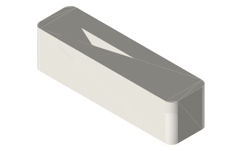
Fluidyne (liquid-piston Stirling) manifold and tees for 1/2 in copper U-tubes
How do I build a fluidyne liquid piston Stirling engine and what tube sizes does it use? · Hardware · basis: West's fluidyne (Harwell, 1970s): a U-tube of water is the displacer, a second water column the power piston, gas spaces above; natural period of the U-tube sets the frequency: T = 2π√(L/2g) with L the water column length
Long Earth Society build part. The water-piston demonstrator. The engines
- sizes
- 4 in table
Notes
- No solid moving parts: water in a U-tube rocks back and forth (the displacer), shuttling the gas above it between a heated and a cooled leg; a third column (the output) is pumped by the pressure swing. Frequency comes from the U-tube: T = 2π√(L/2g): a 400 mm water column oscillates at ~1.1 Hz. The hot leg is heated above the water line, the cold leg left bare or water-cooled.
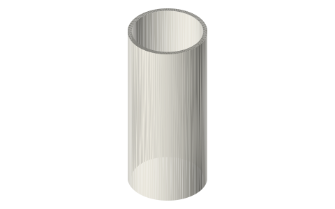
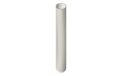
- Tube: 1/2 in Type L copper (15.88 OD, 13.8 ID) for the U legs; glass (test tube or 16 mm borosilicate tube) for a see-through cold leg. Gas space above each leg 2–3 × the swept volume; tuning line (4 mm) between the gas spaces sets the phase (West's 'tuning column'). Output column: another 1/2 in leg with check valves for a pump.
- The printed manifold joins the two legs at the top with a gas passage and the tuning port; the tee adds the output column. Seal copper into the sockets with silicone; everything above the water stays under 60 °C so PETG is fine, the heated copper is below it.
- LES: the no-moving-parts demonstrator next to the thermoacoustic one: same spools, water instead of pistons.
Sizes
| part | size | note |
|---|---|---|
| U legs | 1/2 in copper, 300–500 long | water column |
| manifold | 2 sockets @ 60 mm, 4 mm tuning port | printed |
| output tee | 1/2 in + 4 mm port | pump column |
| period | 2π√(L/2g) | L = water column length |
Where the files are
Other publishers' files are linked, not hosted. "verify" = check the license at the link before commercial use.
| Wikipedia | Fluidyne engine | web | CC BY-SA 4.0 (text) |
| C. D. West | Liquid Piston Stirling Engines (1983) | book, reports (OSTI) | reference / US Gov reports public domain verify |
| Long Earth Society | Engine builds | web, video | LES site |
Free files
★ Free files 2 parts. Generated by Xem Studio from the standard; threads are plain cylinders at major diameter. CC BY 4.0. index.json
| fluidyne-manifold-2x-1-2in-copper | fluidyne displacer manifold: two Ø15.88 (1/2 in copper) sockets 60 mm apart joined by a gas passage, 4 mm tuning port | STEP · STL |
| fluidyne-output-tee-1-2in | output-column tee for 1/2 in copper with a 4 mm side port | STEP · STL |
Plain text: sheet.txt · JSON: /api/geometry?object=fluidyne-manifold
Fits with
Questions
What is a fluidyne engine?
A Stirling engine whose displacer and piston are columns of water in U-tubes; gas above the water is heated and cooled as the water rocks. No solid moving parts; it pumps water.
What sets a fluidyne's frequency?
The U-tube's natural period, T = 2π√(L/2g): a 400 mm water column gives about 1.1 Hz; longer columns are slower.
What tube size for a fluidyne?
1/2 in copper (15.88 mm) legs 300–500 mm long with the gas spaces above; a 4 mm tuning line between the gas spaces sets the phase.