 Xem Studiomeasured geometry
Library › Stirling engines › Thermoacoustic & fluidyne ·
Thermoacoustic stacks (slicer-infill blanks, spiral), resonator lengths and a speaker driver cap for tri-clamp spools
What stack and tube length does a thermoacoustic engine need, and how do I print a honeycomb stack? · Hardware · basis: Standing-wave thermoacoustic engine design (Swift): stack plate spacing ≈ 2–4 thermal penetration depths (δκ ≈ 0.1–0.3 mm in air at 1 bar, 100–300 Hz → gaps 0.5–1.5 mm), stack centred ~λ/8 from the closed end of a λ/4 resonator; stacks printed as a solid blank whose slicer infill IS the honeycomb
Long Earth Society build part. The stacks, driver cap and tube-length table from the LES thermoacoustic builds; the infill trick is LES's. The engines
- sizes
- 3 in table
Notes
- A thermoacoustic engine has no pistons: a stack (many narrow parallel channels) with a hot end and a cold end sits inside a resonator tube; above a critical temperature gradient the gas self-oscillates at the tube's resonance. Load it with a speaker-as-microphone (the driver cap) or a piston on a linear alternator. Driven backwards it pumps heat: a thermoacoustic refrigerator.
- Print the stack from the blank: 1 perimeter, 0 top and 0 bottom layers, infill pattern honeycomb (or grid / triangles), and set the infill density to the cell size you want. Cell pitch ≈ 2 × line width / density for grid; ≈ 1.7 × line width / density for honeycomb. With a 0.4 mm line: 60% → ~1.3 mm grid cells, 45% → 1.8 mm, 30% → 2.7 mm, 80% → 1.0 mm. The density slider is the stack's channel size; no new file needed. Print 0.1–0.15 mm layers so the walls are smooth.
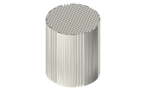
- Stack physics: channel half-width 2–4 × δκ, δκ = √(κ/(π f ρ cp)) = 0.26 mm for air at 1 bar and 100 Hz (0.15 mm at 300 Hz), so cells of 1–1.5 mm at 100 Hz, ~1.0 at 300 Hz. Length 20–50 mm. Centre the stack about λ/8 from the closed (hot) end. Low-conductivity walls: PETG/resin for demonstrators (hot end on a metal plate, stack behind it), ceramic honeycomb (catalytic substrate, 400 cpsi ≈ 1.1 mm cells) for real heat.
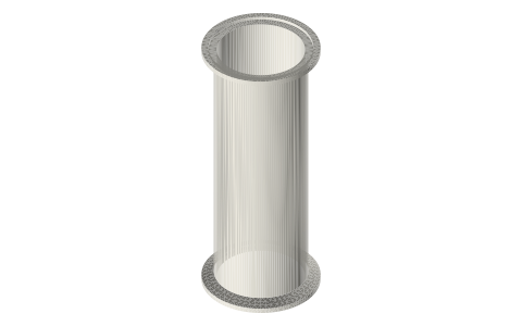
- Resonator: closed-open tube f = c / 4L (λ/4): 100 Hz → 858 mm, 150 Hz → 572, 200 Hz → 429, 300 Hz → 286, 500 Hz → 172 (air, 20 °C, c = 343 m/s). Closed-closed (two caps) is λ/2, twice as long. Tri-clamp spools stack to any length: two or three 2 in × 12 in spools make a 200–300 Hz λ/4 engine with the hot end capped. Heat: nichrome coil or flame on the capped end; cold end a water jacket or the copper-pipe cooler.
- The spiral stack is the template for the classic rolled-Mylar-and-fishing-line stack; the explicit 1.5 mm hex file is a reference for the geometry the infill approximates.
- LES: the stacks, driver cap and tube-length table from the LES thermoacoustic builds; the infill trick is how LES prints them.
Sizes
| spool | bore_mm | stack | lengths_mm | quarter_wave_150hz_mm | half_wave_150hz_mm |
|---|---|---|---|---|---|
| 1.5 | 34.8 | blank + infill (table) | 30 / 40 / 50 | 572.0 | 1143.0 |
| 2 | 47.5 | blank + infill (table) | 30 / 40 / 50 | 572.0 | 1143.0 |
| 3 | 72.9 | blank + infill (table) | 30 / 40 / 50 | 572.0 | 1143.0 |
Where the files are
Other publishers' files are linked, not hosted. "verify" = check the license at the link before commercial use.
| Wikipedia | Thermoacoustic heat engine | web | CC BY-SA 4.0 (text) |
| G. W. Swift (LANL) | Thermoacoustics: A Unifying Perspective for Some Engines and Refrigerators (textbook; DeltaEC software free) | web, software | LANL verify |
| NASA (NTRS, public domain) | Thermoacoustic Stirling heat engine for space power | US Government work, public domain | |
| Long Earth Society | Engine builds | web, video | LES site |
Free files
★ Free files 16 parts. Generated by Xem Studio from the standard; threads are plain cylinders at major diameter. CC BY 4.0. index.json
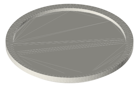
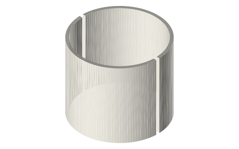
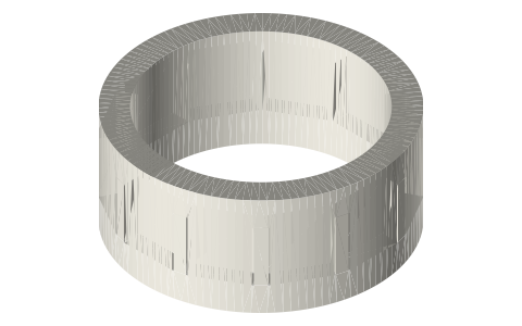
| stack-blank-1.5in-30 | stack blank Ø34.2 × 30 for the 1.5 in bore: slice with 0 top/bottom layers, 1 perimeter, honeycomb or grid infill; density sets the cell size (see table) | STEP · STL |
| stack-blank-1.5in-40 | stack blank Ø34.2 × 40 for the 1.5 in bore: slice with 0 top/bottom layers, 1 perimeter, honeycomb or grid infill; density sets the cell size (see table) | STEP · STL |
| stack-blank-1.5in-50 | stack blank Ø34.2 × 50 for the 1.5 in bore: slice with 0 top/bottom layers, 1 perimeter, honeycomb or grid infill; density sets the cell size (see table) | STEP · STL |
| stack-honeycomb-1.5in-40-c1.5-reference | explicit 1.5 mm hex honeycomb stack 1.5 in × 40 (reference geometry; the blank + infill route is faster) | STEP · STL |
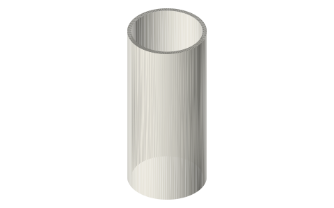
| stack-spiral-1.5in-40-g1.0 | spiral (rolled-sheet) stack 1.5 in, 40 long, 1.0 mm gap (also a template for rolling film + fishing-line spacers) | STEP · STL |
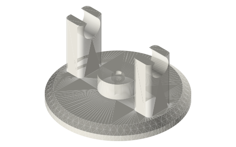
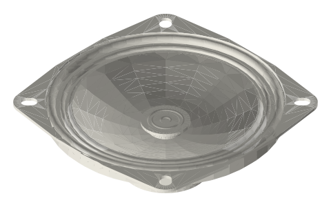
| driver-cap-1.5in-40mm-speaker | 1.5 in ISO 2852 cap with a socket for a 40 mm speaker (thermoacoustic refrigerator driver / engine load) | STEP · STL |
| stack-blank-2in-30 | stack blank Ø46.9 × 30 for the 2 in bore: slice with 0 top/bottom layers, 1 perimeter, honeycomb or grid infill; density sets the cell size (see table) | STEP · STL |
| stack-blank-2in-40 | stack blank Ø46.9 × 40 for the 2 in bore: slice with 0 top/bottom layers, 1 perimeter, honeycomb or grid infill; density sets the cell size (see table) | STEP · STL |
| stack-blank-2in-50 | stack blank Ø46.9 × 50 for the 2 in bore: slice with 0 top/bottom layers, 1 perimeter, honeycomb or grid infill; density sets the cell size (see table) | STEP · STL |
| stack-spiral-2in-40-g1.0 | spiral (rolled-sheet) stack 2 in, 40 long, 1.0 mm gap (also a template for rolling film + fishing-line spacers) | STEP · STL |
| driver-cap-2in-40mm-speaker | 2 in ISO 2852 cap with a socket for a 40 mm speaker (thermoacoustic refrigerator driver / engine load) | STEP · STL |
| stack-blank-3in-30 | stack blank Ø72.3 × 30 for the 3 in bore: slice with 0 top/bottom layers, 1 perimeter, honeycomb or grid infill; density sets the cell size (see table) | STEP · STL |
| stack-blank-3in-40 | stack blank Ø72.3 × 40 for the 3 in bore: slice with 0 top/bottom layers, 1 perimeter, honeycomb or grid infill; density sets the cell size (see table) | STEP · STL |
| stack-blank-3in-50 | stack blank Ø72.3 × 50 for the 3 in bore: slice with 0 top/bottom layers, 1 perimeter, honeycomb or grid infill; density sets the cell size (see table) | STEP · STL |
| stack-spiral-3in-40-g1.0 | spiral (rolled-sheet) stack 3 in, 40 long, 1.0 mm gap (also a template for rolling film + fishing-line spacers) | STEP · STL |
| driver-cap-3in-40mm-speaker | 3 in ISO 2852 cap with a socket for a 40 mm speaker (thermoacoustic refrigerator driver / engine load) | STEP · STL |
Plain text: sheet.txt · JSON: /api/geometry?object=thermoacoustic-stacks-and-resonators
Fits with
Questions
How do I 3D print a thermoacoustic stack?
Print the stack blank with 1 perimeter, 0 top/bottom layers and honeycomb or grid infill; the infill density sets the cell size (0.4 mm line: 60% ≈ 1.3 mm grid cells, 45% ≈ 1.8 mm, 80% ≈ 1.0 mm). No custom geometry needed.
How long should a thermoacoustic engine tube be?
Closed-open (λ/4): L = 343 / (4f): 286 mm for 300 Hz, 429 mm for 200 Hz, 858 mm for 100 Hz in air; closed-closed tubes are twice that.
What channel size should the stack have?
2–4 thermal penetration depths: about 1–1.5 mm in air at 1 bar and 100–300 Hz; finer at higher frequency or pressure.
Where does the stack go in the resonator?
Centred about one-eighth of a wavelength from the closed (hot) end: 107 mm for a 400 mm λ/4 tube.
Can a thermoacoustic engine make electricity?
A speaker in the driver cap becomes a generator (milliwatts), or a piston on the linear alternator kit for real power; NASA's TASHE used a travelling-wave loop with a linear alternator.