 Xem Studiomeasured geometry
Library › Hardware › Stirling & thermoacoustic ·
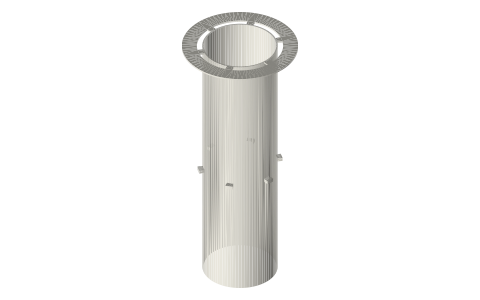
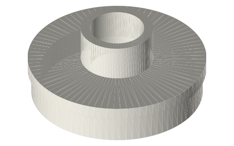
Free-piston displacer liner: Ø40 bore, regenerator inner wall, rim clamped in the tri-clamp joint
How is the displacer cylinder held inside a tri-clamp hot end? · Hardware · basis: Design values of the free-piston generator: displacer bore Ø40.00 (0.30 radial gap to the Ø39.4 displacer), regenerator annulus Ø41.5–Ø47.5, rim at the ISO 2852 flange diameter
Long Earth Society build part. The displacer's cylinder in my free-piston generator. The engines
Exact dimensions. Every file is drawn at true size with no printing tolerance. The holes and pins that meet another part are listed below under Mating features, with the fit each joint needs; open those by your printer's or process's clearance before making the part. Mating features
- sizes
- 5 in table
Notes
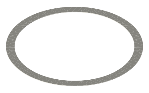
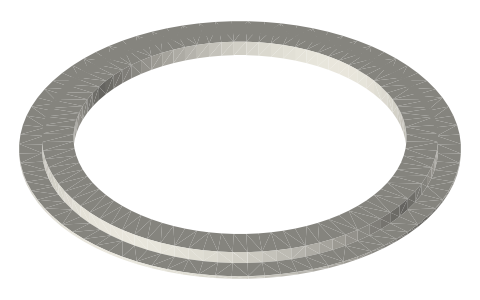
- It hangs from joint A: its Ø64 × 0.8 rim is clamped between two half gaskets exactly like the flexure leaves, so it is centred by the clamp and sealed by the gaskets; six windows in the rim over r 20.75–23.75 let the gas from the regenerator through to the cooler.
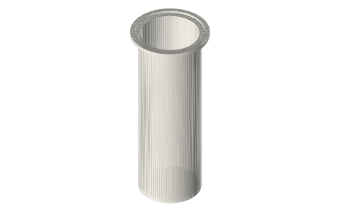
- The tube (Ø40 bore, 0.75 wall) is the regenerator's inner wall and the displacer's bore, from 5 mm above the outer bottom (the gas turns under its end) to the joint.
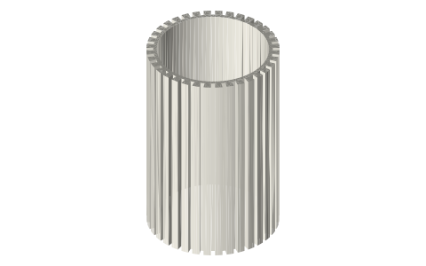
- Six 10° spokes 2 thick at 73.05–75.05 mm carry the 389 screen rings and centre the tube in the bore; below them the heater insert slides onto the tube from the bottom (optional).
- Fits: bore Ø40 is the displacer's designed 0.30 gap (no contact); spokes and rim OD locate in the Ø47.5 bore and the clamp; the rim is clamped.
Sizes
| feature | value |
|---|---|
| bore | Ø40.00 (displacer gap 0.30) |
| tube OD | 41.5 |
| rim | Ø64 × 0.8, 6 windows |
| spokes | 6 × 10°, 2 thick, z 73.05–75.05 |
| bottom end | z 5 (2 above the floor) |
Mating features
Drawn at the exact size. Open press, slide, run and socket features by your process's clearance; leave designed gaps and clamp fits as drawn.
| feature | exact | mates with | fit | files |
|---|---|---|---|---|
| bore | Ø40.00 | displacer Ø39.4 (0.30 radial gap, no contact) | designed | all |
| rim | Ø64 × 0.8 | two half gaskets in joint A; centred on the flange rims by the clamp | clamp | all |
| spoke tips | Ø47.5 | hot spool bore | slide | all |
| tube OD | Ø41.5 | heater insert bore | press | all |
| tube OD | Ø41.5 | regenerator ring bores | slide | all |
| bottom end | 2 above the closed end | gas passage (no contact) | designed | all |
Where the files are
Other publishers' files are linked, not hosted. "verify" = check the license at the link before commercial use.
| Ohio University (Urieli) | Stirling cycle machine analysis: ideal adiabatic and simple analysis (after Urieli & Berchowitz, Stirling Cycle Engine Analysis, 1984) | web | author's site |
| Long Earth Society | Engine builds | web, video | LES site |
Free files
★ Free files 1 parts. Generated by Xem Studio from the standard; threads are plain cylinders at major diameter. CC BY 4.0. index.json
| fpse-liner-40-rim64 | displacer liner: tube Ø40 / Ø41.5 from 5 above S1's outer bottom to the rim; six 10° spokes 2 thick under the regenerator (z 73.05–75.05) out to Ø47.5; rim Ø64 × 0.8 clamped in joint A with six windows over the regenerator annulus | STEP · STL |
Plain text: sheet.txt · JSON: /api/geometry?object=fpse-displacer-cylinder
How it fits
In these build lists
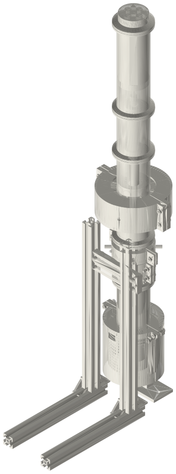
Free-piston Stirling generator, 2 in tri-clamp…A real free-piston Stirling generator in standard 2 in sanitary fittings: closed…You might also need
Questions
Why is the liner clamped in the joint?
The joint centres it on the vessel's axis as accurately as the clamp centres the two spools, and the gaskets seal over it; nothing needs fixing inside the hot end.