 Xem Studiomeasured geometry
Library › Hardware › Stirling & thermoacoustic ·
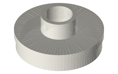
Free-piston displacer: Ø39.4 sealed shell and cap for a 2 in tri-clamp engine
What does the displacer of a pressurised free-piston Stirling look like? · Hardware · basis: Design values of the free-piston generator; collapse margin from the thin-tube buckling relation p = 2E/(1 − ν²)·(t/D)³ at E 200 GPa (assumed)
Used in Long Earth Society builds. Stirling engine displacer build (8" × 6"), aluminum flashing · Stirling engine displacer build (full walkthrough) · Designing a displacer for a 3-foot free-piston Stirling engine
Exact dimensions. Every file is drawn at true size with no printing tolerance. The holes and pins that meet another part are listed below under Mating features, with the fit each joint needs; open those by your printer's or process's clearance before making the part. Mating features
- sizes
- 4 in table
Notes
- Ø39.4 shell, 0.8 wall, 209.9 long with its cap: it reaches from the bottom of the hot spool (the expansion space under it) through joint A into the 3 in cooler spool, where its cold face meets the compression space under leaf B.
- It runs with a designed 0.30 radial gap in the liner and the cooler insert, never touching: leaf B at joint B holds its cold end on the axis and the rod's gland holds the other end of the rod.
- Sealed with the gas it was assembled in. Thin-tube collapse pressure of the shell: about 37 bar for a wall of modulus 200 GPa, against 16 bar absolute at the relief setting; the cap's flange takes the end load on the shell's rim.
- Moving mass with its rod, plug, stinger and gas-spring piston: 365 g (at 7.9 g/cm³).
Sizes
| part | size |
|---|---|
| shell | Ø39.4 × 206.9, wall 0.8 |
| cap | spigot Ø37.8, flange Ø39.4 × 3, boss Ø16 × 8 |
| gap | 0.30 radial (designed) |
| travel | ±6 room, ±4.47 at the design point |
Mating features
Drawn at the exact size. Open press, slide, run and socket features by your process's clearance; leave designed gaps and clamp fits as drawn.
| feature | exact | mates with | fit | files |
|---|---|---|---|---|
| shell OD | Ø39.4 | liner and cooler-insert bores Ø40.00 (0.30 radial gap) | designed | fpse-displacer-shell* |
| shell bore | Ø37.8 | cap spigot (sealed joint) | press | fpse-displacer-shell* |
| spigot | Ø37.8 × 6 | shell bore (sealed joint) | press | fpse-displacer-cap* |
| rod socket | Ø12 × 14 | displacer rod Ø12 | press | fpse-displacer-cap* |
| boss top face | Ø16 | leaf B's hub, clamped by the collar | clamp | fpse-displacer-cap* |
Where the files are
Other publishers' files are linked, not hosted. "verify" = check the license at the link before commercial use.
| Ohio University (Urieli) | Stirling cycle machine analysis: ideal adiabatic and simple analysis (after Urieli & Berchowitz, Stirling Cycle Engine Analysis, 1984) | web | author's site |
| Long Earth Society | Engine builds | web, video | LES site |
Free files
★ Free files 2 parts. Generated by Xem Studio from the standard; threads are plain cylinders at major diameter. CC BY 4.0. index.json
| fpse-displacer-shell-39.4 | displacer shell Ø39.4 × 206.9, wall 0.8, closed hot end 2 (1.0 outer round) | STEP · STL |
| fpse-displacer-cap-39.4 | displacer cap: spigot Ø37.8 × 6 (2 wall) into the shell, flange Ø39.4 × 3 on its rim, boss Ø16 × 8 with the Ø12 × 14 rod socket | STEP · STL |
Plain text: sheet.txt · JSON: /api/geometry?object=fpse-displacer
How it fits
In these build lists
Free-piston Stirling generator, 2 in tri-clamp…A real free-piston Stirling generator in standard 2 in sanitary fittings: closed…You might also need
Questions
Why is the displacer sealed?
Vented, its whole inside would be dead volume in the working space. Sealed, it only has to carry the charge pressure; its cap's flange rests on the shell's rim so the load goes straight into the shell.