 Xem Studiomeasured geometry
Library › Hardware › Stirling & thermoacoustic ·
Free-piston displacer gas spring: double-acting Ø18 cylinder, gland and piston in a 2 in tri-clamp spool
What sets the displacer's spring in a free-piston Stirling engine? · Hardware · basis: Gas-spring stiffness k = γ p (A²/V₁ + (A − a)²/V₂) (two closed columns either side of the piston); tuned with the Redlich & Berchowitz linear dynamics of the generator
Used in Long Earth Society builds. Designing a displacer for a 3-foot free-piston Stirling engine · Designing a free-piston Stirling engine
Exact dimensions. Every file is drawn at true size with no printing tolerance. The holes and pins that meet another part are listed below under Mating features, with the fit each joint needs; open those by your printer's or process's clearance before making the part. Mating features
- sizes
- 5 in table
Notes
- The displacer must resonate a little below the running frequency so that it leads the piston; with 365 g moving that takes about 28 kN/m at 10 bar helium. A flexure that stiff would be overstressed at the displacer's stroke, so the spring is gas: two 30 mm columns of the working charge either side of a Ø18 piston on the end of the stinger (7.63 + 7.42 cm³).
- It scales with the charge, as the engine's other gas forces do, so the displacer stays in tune from 1 to 10 bar. Its compression ratio is mild: ±15 % of the column at the design stroke.
- Tuning: the column height sets the frequency of the displacer and so its phase lead; my analysis puts 30 mm at about 70° lead. Shorter columns make it stiffer (less lead), longer columns softer. The analysis on the performance page shows the effect of ±10 % displacer mass.
- The cylinder is pressed into the top spool with its vent flats letting the bounce gas past to the port cap; the gland closes its bottom with a spigot and three M3 × 16; the stinger runs in the gland's Ø3 bore. Both clearances (piston and stinger) leak only between gas springs at the same mean pressure.
Sizes
| part | size |
|---|---|
| cylinder | Ø47.5 × 93.0, bore Ø18 |
| piston | Ø18 × 25 |
| gland | Ø47.5 × 10 + Ø18 × 3 spigot |
| columns | 2 × 30 mm |
| stiffness at 10 bar He | 27.9 kN/m |
Mating features
Drawn at the exact size. Open press, slide, run and socket features by your process's clearance; leave designed gaps and clamp fits as drawn.
| feature | exact | mates with | fit | files |
|---|---|---|---|---|
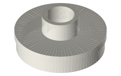
| OD | Ø47.5 (four 0.75 vent flats) | S6 spool bore | press | fpse-gas-spring-cylinder* |
| bore | Ø18 | gas-spring piston Ø18 × 25 (seal) | run | fpse-gas-spring-cylinder* |
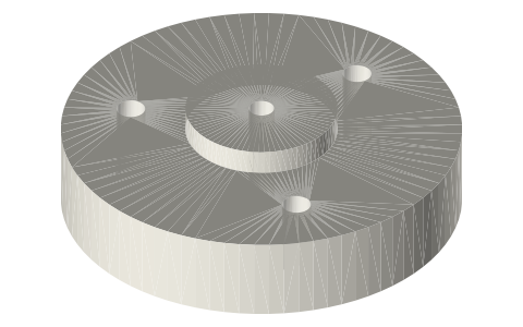
| tapped holes | 3 × Ø2.5 × 10 on r 16 | M3 × 16 up through the gland | designed | fpse-gas-spring-cylinder* |
| spigot | Ø18 × 3 | cylinder bore (seal) | press | fpse-gas-spring-gland* |
| OD | Ø47.5 | S6 spool bore | slide | fpse-gas-spring-gland* |
| bore | Ø3 × 13 | stinger (seal) | run | fpse-gas-spring-gland* |
| screw holes | 3 × Ø3.4 on r 16 | M3 clearance (ISO 273 medium) | designed | fpse-gas-spring-gland* |
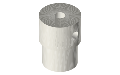
| OD | Ø18 × 25 | cylinder bore (seal) | run | fpse-gas-spring-piston* |
| stinger socket | Ø3 × 10 | stinger, held by an M3 grub | slide | fpse-gas-spring-piston* |
Where the files are
Other publishers' files are linked, not hosted. "verify" = check the license at the link before commercial use.
| Proc. IMechE Part A | Redlich & Berchowitz (1985), Linear dynamics of free-piston Stirling engines | journal; method cited verify | |
| Wikipedia | Hagen–Poiseuille flow between parallel plates (clearance-seal leakage Q = π D δ³ Δp / 12 μ L) | web | CC BY-SA 4.0 (text) |
| Long Earth Society | Engine builds | web, video | LES site |
Free files
★ Free files 3 parts. Generated by Xem Studio from the standard; threads are plain cylinders at major diameter. CC BY 4.0. index.json
| fpse-gas-spring-cylinder-18 | gas-spring cylinder: Ø47.5 × 93.0 pressed into S6, blind Ø18 bore 88.0 deep, 3 × M3 tapped (Ø2.5 × 10) on r 16 in its bottom, four 0.75 vent flats on the OD | STEP · STL |
| fpse-gas-spring-gland-18 | gland plate: Ø47.5 × 10, Ø18 × 3 spigot into the cylinder's bore, Ø3 stinger bore (running fit), 3 × Ø3.4 on r 16 | STEP · STL |
| fpse-gas-spring-piston-18 | gas-spring piston Ø18 × 25 (running fit in the cylinder), Ø3 × 10 stinger socket from below, M3 tapped radial hole (Ø2.5) at 5 | STEP · STL |
Plain text: sheet.txt · JSON: /api/geometry?object=fpse-displacer-gas-spring
How it fits
In these build lists
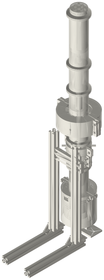
Free-piston Stirling generator, 2 in tri-clamp…A real free-piston Stirling generator in standard 2 in sanitary fittings: closed…You might also need
Questions
Why double-acting?
With one closed column above and the bounce space below, the bounce pressure (which the piston drives) would push the displacer along with the piston and cancel its drive. Closing both sides makes the spring answer to the displacer alone.