 Xem Studiomeasured geometry
Library › Hardware › Stirling & thermoacoustic ·
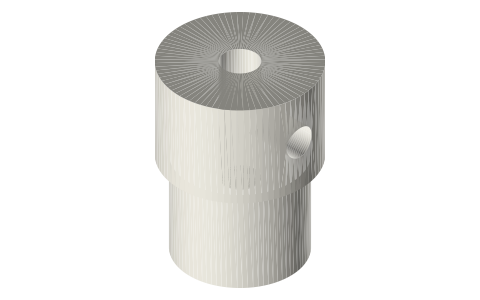
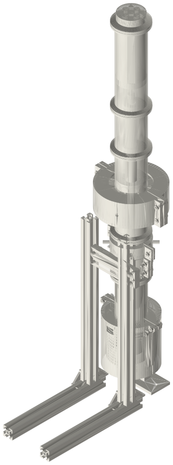
Free-piston displacer rod, plug and stinger: Ø12 rod through the power piston, Ø3 stinger to the gas spring
How does the displacer of a Beale free-piston Stirling get its drive and its spring? · Hardware · basis: Beale free-piston layout (rod area drive), Redlich & Berchowitz linear dynamics; stinger stiffness from Euler beam relations
Long Earth Society build part. The displacer drive of my free-piston generator. The engines
Exact dimensions. Every file is drawn at true size with no printing tolerance. The holes and pins that meet another part are listed below under Mating features, with the fit each joint needs; open those by your printer's or process's clearance before making the part. Mating features
- sizes
- 3 in table
Notes
- The rod's area (Ø12) is the displacer's drive: the working gas pushes on it from below and the bounce space from above, and that difference, swinging with the piston, pushes the displacer ahead of the piston (the Beale free-piston principle).
- It runs up through leaf B's hub (clamped there by the cap's boss and a collar) and the piston's Ø12 hub bore, a running fit 76 mm long that is also the seal between working and bounce space, to the plug at its top.
- The Ø3 stinger joins the plug to the gas-spring piston: stiff along its length, soft sideways (87 mm free), so the gas spring's own cylinder does not fight the rod's alignment through the piston.
Sizes
| part | size |
|---|---|
| rod | Ø12 / Ø10 × 260.45 |
| plug | Ø10 × 8 spigot, Ø12 × 8 head |
| stinger | Ø3 × 87.05 |
Mating features
Drawn at the exact size. Open press, slide, run and socket features by your process's clearance; leave designed gaps and clamp fits as drawn.
| feature | exact | mates with | fit | files |
|---|---|---|---|---|
| rod OD | Ø12 | piston hub bore Ø12 × 76 (seal and guide) | run | fpse-displacer-rod* |
| rod OD | Ø12 | leaf B's hub and the collar (M3 grub) | slide | fpse-displacer-rod* |
| rod OD | Ø12 | tube rod bore Ø14 (no contact) | designed | fpse-displacer-rod* |
| rod bore | Ø10 | plug spigot | press | fpse-displacer-rod* |
| spigot | Ø10 × 8 | rod bore | press | fpse-rod-plug* |
| stinger socket | Ø3 × 10 | stinger, held by an M3 grub | slide | fpse-rod-plug* |
| grub hole | Ø2.5 | M3 tap drill | designed | fpse-rod-plug* |
| stinger | Ø3 | gland bore Ø3 × 13 (seal) | run | fpse-stinger* |
| stinger ends | Ø3 × 10 | plug and gas-spring piston sockets | slide | fpse-stinger* |
Where the files are
Other publishers' files are linked, not hosted. "verify" = check the license at the link before commercial use.
| Proc. IMechE Part A | Redlich & Berchowitz (1985), Linear dynamics of free-piston Stirling engines | journal; method cited verify | |
| Long Earth Society | Engine builds | web, video | LES site |
Free files
★ Free files 3 parts. Generated by Xem Studio from the standard; threads are plain cylinders at major diameter. CC BY 4.0. index.json
| fpse-displacer-rod-12x10 | displacer rod: tube Ø12 / Ø10 × 260.45: through leaf B's hub and the piston's hub bore (running fit) | STEP · STL |
| fpse-rod-plug-12 | rod plug: Ø10 × 8 spigot into the rod's top, Ø12 × 8 head with a Ø3 × 10 stinger socket and an M3 tapped radial hole (Ø2.5) | STEP · STL |
| fpse-stinger-3x87.05 | stinger: Ø3 × 87.05: rod plug to the gas-spring piston, through the gland | STEP · STL |
Plain text: sheet.txt · JSON: /api/geometry?object=fpse-displacer-rod
How it fits
In these build lists
Free-piston Stirling generator, 2 in tri-clamp…A real free-piston Stirling generator in standard 2 in sanitary fittings: closed…You might also need
Questions
Why a stinger?
The rod is guided by the piston's bore and the gas-spring piston by its own cylinder, in a different spool; a slender link between them carries the spring force without forcing the two guides into line.