 Xem Studiomeasured geometry
Library › Stirling engines › Tri-clamp engine parts ·
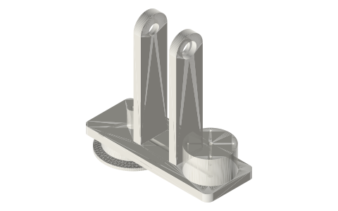
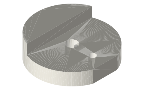
Gamma crank head for a 2 in tri-clamp spool: rod gland, crankshaft towers and power-cylinder seat in one part
What holds the crankshaft and power cylinder on a 2 inch tri-clamp gamma Stirling engine? · Hardware · basis: ISO 2852 cap face (the end-cap profile) on a pedestal clear of the two-bolt clamp; 625 bearing (5 × 16 × 5) pockets; Ø20 × 45 flanged liner seat (flange Ø44, 4 × M3 on Ø36); all positions from the gamma crank train worked out in tools/gamma_geom.py
Long Earth Society build part. The crank head of the LES 2 in gamma. The engines
Exact dimensions. Every file is drawn at true size with no printing tolerance. The holes and pins that meet another part are listed below under Mating features, with the fit each joint needs; open those by your printer's or process's clearance before making the part. Mating features
- sizes
- 7 in table
Notes
- One part closes the spool's cold end and carries the whole crank: the ISO 2852 face clamps to the spool like an end cap; a Ø50.8 pedestal rises clear of the clamp to a deck at 14–22 mm.
- Displacer rod: a Ø3 bore runs straight through the cap, pedestal, deck and a Ø10 boss to 40 mm, a 40 mm clearance-seal gland for the Ø3 rod (the running fit is listed under Mating features).
- Crankshaft: two towers (x 15.5–23.5 and 55.5–63.5) with Ø16 × 5 pockets for 625 bearings put a Ø5 × 80 shaft 127.5 mm above the face, along the deck. Tower A's pocket opens toward the rod axis, tower B's toward the power cylinder, so the crank discs and spacers on the two shaft ends hold the shaft between the bearings.
- Cranks are overhung: the displacer disc on the x = 3.5 end puts its con-rod on the rod axis, the power disc on the x = 83.5 end puts its con-rod on the power cylinder axis (x 87); the flywheel turns between the towers, Ø150 clear of the deck by 30.5 mm.
- Power cylinder: the Ø20 × 45 liner's flange sits on a Ø44 seat (top 47.8 mm) with four M3 tapped holes (Ø2.5) on R18; the seat is the cylinder head. A Ø4 passage runs from the cap face at x 15 up into the deck, along it at z 18, and up into the liner: the transfer port, with no tube.
- Exact dimensions: pockets, bores and holes are drawn at the bearing, rod and tap-drill sizes; their fits are under Mating features.
Sizes
| feature | size_mm | position_mm |
|---|---|---|
| ISO 2852 face | 2 in (Ø64 rim) | z 0 |
| pedestal | Ø50.8 | z 4.5–14 |
| deck | 141 × 54 × 8 | x -30..111 |
| rod gland | Ø3 × 40 | on the axis |
| 625 pockets | Ø16 × 5 | z 127.5; x 15.5–20.5 and 58.5–63.5 |
| liner seat | Ø44, 4 × M3 tapped on R18 | x 87, top z 47.8 |
| transfer passage | Ø4 | x 15 → 87 at z 18 |
Mating features
Drawn at the exact size. Open press, slide, run and socket features by your process's clearance; leave designed gaps and clamp fits as drawn.
| feature | exact | mates with | fit | files |
|---|---|---|---|---|
| head face | ISO 2852 | ferrule face + Type B gasket | clamp | all |
| rod gland | Ø3 × 41 | Ø3 displacer rod (clearance seal) | run | all |
| tower bearing pockets | Ø16 × 5 | 625 bearing | press | all |
| tower shaft clearance | Ø11.2 | Ø5 shaft (no contact) | designed | all |
| liner seat holes | Ø2.5 × 8 | M3 tap drill (liner flange screws) | designed | all |
| transfer passage | Ø4 | engine space to the liner (gas path) | designed | all |
Where the files are
Other publishers' files are linked, not hosted. "verify" = check the license at the link before commercial use.
| Wikipedia | Stirling engine | web | CC BY-SA 4.0 (text) |
| ISO | ISO 2852 clamp pipe couplings (face profile) | standard | ISO verify |
| Long Earth Society | Engine builds | web, video | LES site |
Free files
★ Free files 1 parts. Generated by Xem Studio from the standard; threads are plain cylinders at major diameter. CC BY 4.0. index.json
| gamma-crank-head-2in | 2 in gamma crank head: ISO 2852 cap face, Ø50.8 pedestal to 14, deck 141 × 54 × 8, Ø3 rod gland through cap and a Ø10 boss to 40, two towers with 625 pockets for a Ø5 crankshaft 127.5 above the face, Ø44 liner seat at x 87 (top 47.8, 4 × M3 tapped on R18), Ø4 transfer passage from the cap face to the liner | STEP · STL |
Plain text: sheet.txt · JSON: /api/geometry?object=gamma-crank-head
How it fits
In these build lists
Gamma Stirling, 2 in tri-clampHot spool with a shell displacer, a crank head that carries the crankshaft, the …You might also need
Questions
How does the power cylinder connect to the displacer space on the tri-clamp gamma?
Through a Ø4 passage inside the crank head, from the cap face under the displacer to the liner seat; there is no transfer tube.
What bearings does the gamma crank head take?
Two 625s (5 × 16 × 5) in Ø16 × 5 pockets, one per tower, on a Ø5 crankshaft.
How high is the crankshaft on the 2 in gamma?
127.5 mm above the ISO 2852 face, far enough that the Ø3 × 100 displacer rod reaches its clevis and the Ø150 flywheel clears the deck.