 Xem Studiomeasured geometry
Library › Stirling engines › Thermoacoustic & fluidyne ·
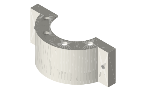
Thermoacoustic hot-head shroud: flame shroud and flue for a vertical 2 in tri-clamp core
How do I heat the hot exchanger of a vertical thermoacoustic core with a propane torch? · Hardware · basis: Bore = ASME BPE 2 in tube OD Ø50.8; positions from the loop layout in tools/gen_ta_family.py; ISO 273 medium clearance for M4
Long Earth Society build part. The flame shroud on my looped thermoacoustic engine. The engines
Exact dimensions. Every file is drawn at true size with no printing tolerance. The holes and pins that meet another part are listed below under Mating features, with the fit each joint needs; open those by your printer's or process's clearance before making the part. Mating features
- sizes
- 5 in table
Notes
- The loop's core stands vertical with its hot exchanger above the thermal buffer tube, hot end up, so the buffer tube does not convect (Backhaus & Swift ran theirs the same way). A torch cannot fire straight up at the middle of a vertical tube, so the shroud does it: a closed band round the tube at the hot exchanger, with a flue that comes down beside the loop to a torch standing on the bench.
- Flame and hot gas go up the Ø35 flue (132.6 mm), into the chamber, round the tube over a 40 mm band (the top 20 mm of the buffer tube, the hot exchanger, the first 10 mm of the regenerator) and out of the vents in the top. No clamp, gasket or jacket is inside the band.
- Two halves split across the tube: the front half carries the flue; one M4 × 25 and nut each side close them on the tube. The end walls are bored at the tube OD.
- What it is made of is the builder's choice; the file is the geometry. It runs at flame temperature.
Sizes
| feature | value |
|---|---|
| band | 40 tall, Ø80 round the tube |
| flue | Ø40 / Ø35 × 132.6, 100 in front of the tube axis |
| walls | 2.5 |
| vents | 8 × Ø6 on r 31.5, 3 × Ø8 over the lobe |
| bolts | M4 × 25 + nut, one each side |
Mating features
Drawn at the exact size. Open press, slide, run and socket features by your process's clearance; leave designed gaps and clamp fits as drawn.
| feature | exact | mates with | fit | files |
|---|---|---|---|---|
| end-wall bores | Ø50.8 | 2 in tube OD | slide | all |
| split | 1.0 total (0.5 per half) | the other half | clamp | all |
| ear holes | Ø4.5 | M4 clearance (ISO 273 medium) | designed | all |
| flue | Ø40 / Ø35 | torch flame from the torch stand below (no contact) | designed | ta-shroud-2in-front* |
| vents | 8 × Ø6, 3 × Ø8 | exhaust (no contact) | designed | all |
Where the files are
Other publishers' files are linked, not hosted. "verify" = check the license at the link before commercial use.
| J. Acoust. Soc. Am. (S. Backhaus, G. W. Swift) | A thermoacoustic-Stirling heat engine: Detailed study, JASA 107(6), 3148 (2000): regenerator |Z| 15–30 ρc/A with p and U nearly in phase, thermal buffer tube, inertance and compliance, jet pump against Gedeon streaming | journal article; numbers cited verify | |
| Long Earth Society | Engine builds | web, video | LES site |
Free files
★ Free files 2 parts. Generated by Xem Studio from the standard; threads are plain cylinders at major diameter. CC BY 4.0. index.json
| ta-shroud-2in-front | front half (y ≥ 0.5): 40 tall band round the Ø50.8 tube, Ø80 chamber joined to a Ø40 lobe at y 100, 2.5 walls; Ø40 / Ø35 flue 132.6 long down from the chamber; vents in the top; ears with Ø4.5 | STEP · STL |
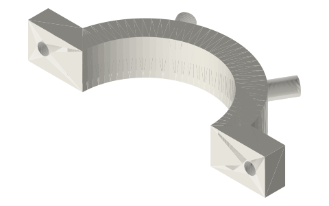
| ta-shroud-2in-back | back half (y ≤ −0.5) of the same band: Ø80 chamber, vents, ears with Ø4.5 | STEP · STL |
Plain text: sheet.txt · JSON: /api/geometry?object=thermoacoustic-hot-shroud
How it fits
In these build lists
Thermoacoustic traveling-wave loop, 2 in…A looped traveling-wave thermoacoustic engine in 2 in tri-clamp, torch-heated, w…Thermoacoustic traveling-wave loop, 2 in…The looped traveling-wave thermoacoustic engine with the free-piston's flexure-s…Thermoacoustic-Stirling hybrid loop with…The looped traveling-wave engine with a flat membrane clamped in the loop to sto…You might also need

Questions
Why not heat it from below?
The hot exchanger is half way up a vertical core, above the buffer tube; a flame from below would heat the lower clamp, jacket and buffer tube first.
Where does the torch go?
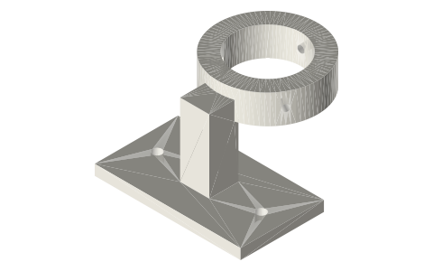
On the bench under the flue, its head in the torch stand's ring with the ring top 25 mm below the flue.