 Xem Studiomeasured geometry
Library › Hardware › Stirling & thermoacoustic ·
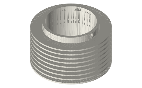
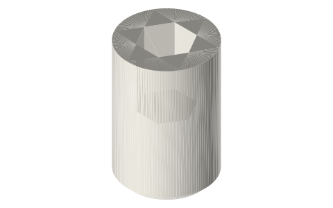
Hot-end fin sleeve for a 2 in tri-clamp cup: slide-on ring fins, set-screw held
How do I put fins on the hot end of a tri-clamp Stirling engine without a custom finned fitting? · Hardware · basis: ASME BPE 2 in tube OD Ø50.8 (the sleeve's bore); fin size and pitch are design values from the sealed generator layout; M4 set screws ISO 4026
Long Earth Society build part. The optional fins on my sealed generator's hot end: a sleeve on a plain cup. The engines
Exact dimensions. Every file is drawn at true size with no printing tolerance. The holes and pins that meet another part are listed below under Mating features, with the fit each joint needs; open those by your printer's or process's clearance before making the part. Mating features
- sizes
- 6 in table
Notes
- A separate heat exchanger for the closed hot end of a plain 2 in cup: a sleeve whose bore is exactly the tube's Ø50.8 slides over the closed end, nine Ø80 ring fins catch the flame gas, and three M4 set screws in a band above the fins hold it. The cup stays a plain, standard closed-end spool; the sleeve can be made any way you like.
- On the sealed generator it sits on the cup-2in-150 from 1.5 mm above the outer bottom (clear of the 1.5 mm round) to 7 mm above the top fin, 49.0 mm in all; the fins cover the bottom 43.5 mm, inside the burner shroud, 4 mm from the shroud's wall.
- The fins are Ø80 so that, starting from the sleeve's Ø56.8 hub, they have the same area as Ø76 fins grown straight off the tube.
- It is optional: the engine runs on the bare cup with less power. The set screws line up with three of the shroud's exhaust windows, so they can be reached with the shroud in place.
- Fits: the bore slides on the tube OD (slide fit), the set screws clamp it.
Sizes
| feature | value |
|---|---|
| bore | Ø50.8 (tube OD) |
| length | 49.0 |
| wall | 3.0 |
| fins | 9 × Ø80 × 1.5, 5 pitch |
| set screws | 3 × M4, 0 / 120 / 240° |
| fits | cup-2in-150 (and any 2 in tube) |
Mating features
Drawn at the exact size. Open press, slide, run and socket features by your process's clearance; leave designed gaps and clamp fits as drawn.
| feature | exact | mates with | fit | files |
|---|---|---|---|---|
| bore | Ø50.8 = the 2 in tube OD | cup-2in-150 tube OD (over its closed end) | slide | all |
| set-screw holes | 3 × Ø3.3 at 0 / 120 / 240° | M4 tap drill; M4 × 4 set screws onto the tube OD | clamp | all |
| fins | 9 × Ø80 × 1.5 at 5 pitch | burner shroud Ø88 bore: 4 mm gas annulus | designed | all |
| top band to the shroud lid | 1.0 | shroud lid (no contact) | designed | all |
Where the files are
Other publishers' files are linked, not hosted. "verify" = check the license at the link before commercial use.
| ISO (via iTeh sample) | ISO 2852 clamp liners: face profile and flange / groove diameters | standard excerpt; dimensions are facts | |
| ASME | BPE Bioprocessing Equipment (clamp fitting dimensions, tube OD and wall) | standard | ASME; dimensions are facts verify |
| Long Earth Society | Engine builds | web, video | LES site |
Free files
★ Free files 1 parts. Generated by Xem Studio from the standard; threads are plain cylinders at major diameter. CC BY 4.0. index.json
| hot-fin-sleeve-2in-80x9 | hot-end fin sleeve for the 2 in tube: bore Ø50.8 (the tube OD) × 49.0, 3 mm wall, 9 ring fins Ø80 × 1.5 at 5 pitch, 7 mm band over the top fin with 3 × M4 tapped (Ø3.3) at 0 / 120 / 240° | STEP · STL |
Plain text: sheet.txt · JSON: /api/geometry?object=tri-clamp-hot-fin-sleeve
How it fits
In these build lists
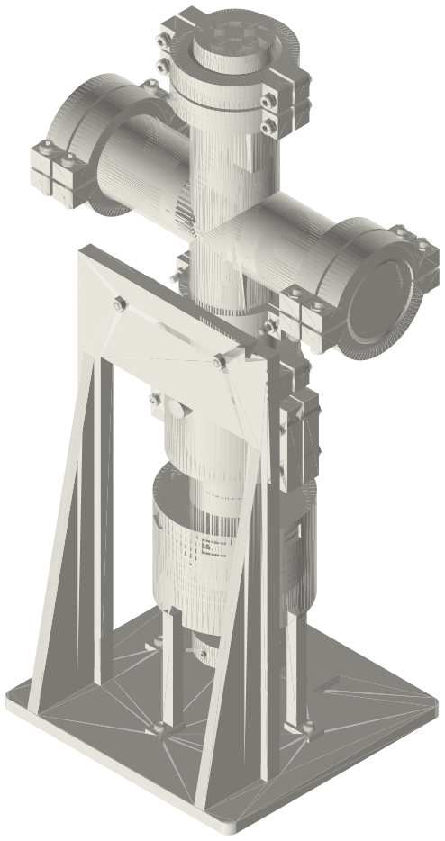
Tri-clamp sealed diaphragm generator, 2 inA sealed, pressurised gamma Stirling generator in 2 in tri-clamp: a plain closed…You might also need
Questions
Do I need it?
No. It is an optional heat exchanger; without it the flame heats the bare cup and the engine makes less power.
Why not fins on the cup itself?
A sanitary fabricator makes plain spools and closed-end cups from stock tube; fins built onto one are not something they make. A separate sleeve keeps the cup standard and lets the fins be made any way.
How is it held?
Three M4 set screws onto the tube OD; its bore is the tube OD exactly (slide fit).