 Xem Studiomeasured geometry
Tri-clamp sealed diaphragm generator, 2 in
A sealed, pressurised gamma Stirling generator in 2 in tri-clamp: a finned one-piece hot head over a torch, a power membrane between the working space and a sealed cross, and a 2208 gimbal motor geared to the crank inside the cross, its leads out through a sealed pass-through.
Membrane 2 in at 12 mm: 11.33 mL swept · displacer Ø46 × 120 at 12 mm: 21.3 mL · dead volume 51.5 mL · swept / dead 0.220 · charge 2 bar gauge · Schmidt (600–700 K / 320 K): ±0.50–0.56 bar, 0.57–0.70 J per cycle · at 900 rpm about 4–8 W at the crank (West / Beale); 2208 gimbal generator at 2520 rpm, 19.7 V open circuit, about 2.1–5.5 W at 14–18 V out of 4–8 W at the crank
Exact dimensions. Every part is drawn at true size with no printing tolerance; each part's page lists its mating features and the fit each joint needs, so open those by your process's clearance before making the parts.
54 parts, every one a file here · all STL URLs · Markdown · tick lines as you go (saved in this browser)
| subsystem | object | parts | qty | note | |
|---|---|---|---|---|---|
| None | Frame for the 2 in tri-clamp sealed diap | sealed-generator-frame-2in STEP · STL | 1 | base, wall, gussets | |
| None | Torch stand for a horizontal tri-clamp h | torch-stand-40 STEP · STL | 1 | on the base under the hot head, post toward +Y | |
| None | Socket head cap screws | shcs-m4x10 STEP · STL | 5 | torch stand (2) and shroud feet (3) to the base | |
| None | Set screws (grub screws) | set-m4x10 STEP · STL | 3 | centre the torch head in the stand ring | |
| None | Burner shroud for a finned 2 in tri-clam | burner-shroud-2in STEP · STL | 1 | round the fins, on its three feet | |
| None | Finned tri-clamp hot head | hot-head-2in-149.74 STEP · STL | 1 | face up; the displacer inside | |
| None | Tri-clamp jacket shell | jacket-half-2in-56 STEP · STL | 2 | round the hot head under the clamp; the fill is the builder's choice | |
| None | Tri-clamp jacket shell | jacket-port-cap STEP · STL | 2 | one per jacket half | |
| None | Socket head cap screws | shcs-m4x30 STEP · STL | 4 | jacket ears | |
| None | Hex nuts | nut-m4 STEP · STL | 6 | jacket ears (4), hanger ears (2) | |
| None | Tri-clamp displacer | displacer-shell-2in-120 STEP · STL | 1 | Ø46 × 120, 0.75 radial gap, 12 stroke | |
| None | Tri-clamp displacer | displacer-cap-2in STEP · STL | 1 | closes the shell, holds the rod | |
| None | Crankshafts Ø3 | crankshaft-3x60 STEP · STL | 1 | displacer rod (Ø3 × 60), through the membrane and the crosshead's guide | |
| None | Tri-clamp membrane with a centre hole | membrane-2in-hole5 STEP · STL | 1 | clamped between the hot head and the cross, in place of a gasket | |
| None | Diaphragm crosshead hub and tapped backi | crosshead-2in-p29.25 STEP · STL | 1 | crankcase side of the membrane: Ø3 guide (the bleed), con-rod pin on its arm | |
| None | Diaphragm crosshead hub and tapped backi | backing-2in-m2-tapped STEP · STL | 1 | working side of the membrane, M2 tapped | |
| None | Socket head cap screws | shcs-m2x6 STEP · STL | 3 | heads on the crosshead, into the backing disc | |
| None | Sanitary clamp crosses (9MP) | cross-2in STEP · STL | 1 | the crankcase: run vertical, branches along the crankshaft | |
| None | Motor-mount plate for a 2 in tri-clamp c | motor-mount-plate-2in-2208 STEP · STL | 1 | on the top of the cross; the motor hangs from it | |
| None | Tri-clamp port cap | port-cap-2in-4x-npt18 STEP · STL | 1 | on the motor-mount plate | |
| None | NPT male thread envelopes 1/8 to 1 in (A | npt-1-8-male STEP · STL | 4 | the 1/8 NPT stems of the fill valve, the pressure gauge, the relief valve and the sealed electrical pass-through (the bodies are the builder's choice) | |
| None | Tri-clamp end cap | tc-cap-2in-flat STEP · STL | 2 | close the two bearing plates | |
| None | Tri-clamp gasket | tc-gasket-2in STEP · STL | 6 | cross–mount plate, mount plate–port cap, two cross–bearing plate, two bearing plate–end cap | |
| None | Tri-clamp clamp | clamp-half-2in STEP · STL | 14 | seven joints, two halves each | |
| None | Socket head cap screws | shcs-m5x30 STEP · STL | 14 | clamp bolts | |
| None | Hex nuts | nut-m5 STEP · STL | 16 | clamp nuts (14), hanger bar (2) | |
| None | Clamp-in bearing plate | bearing-plate-2in-623 STEP · STL | 2 | one in each branch, spigot inward | |
| None | Ball bearings | bearing-623 STEP · STL | 8 | bearing plates (4), con-rod eyes (4) | |
| None | Inner crank webs for the tri-clamp cross | inner-crank-web-hub-r6 STEP · STL | 2 | −X on the displacer pin side, +X on the diaphragm pin | |
| None | Inner crank webs for the tri-clamp cross | inner-crank-web-link-r6 STEP · STL | 1 | between the two pins, 90° apart | |
| None | Dowel pins | dowel-3x12 STEP · STL | 2 | displacer crank pin, displacer clevis pin | |
| None | Dowel pins | dowel-3x16 STEP · STL | 1 | diaphragm crank pin | |
| None | Dowel pins | dowel-3x10 STEP · STL | 1 | crosshead pin | |
| None | Connecting rods 30 to 80 mm centres with | conrod-40 STEP · STL | 1 | displacer, in its clevis gap | |
| None | Connecting rods 30 to 80 mm centres with | conrod-60 STEP · STL | 1 | diaphragm, beside the displacer clevis | |
| None | Rod clevises for a Ø2 or Ø3 rod or a Ø5 | rod-clevis-3mm STEP · STL | 1 | on the displacer rod | |
| None | Crankshafts Ø3 | crankshaft-3x80 STEP · STL | 1 | +X crankshaft: hub web to the pocket flywheel | |
| None | Displacer rods Ø2 × 60 | rod-3x100 STEP · STL | 1 | −X crankshaft: hub web to the pocket flywheel | |
| None | Crankcase flywheels | crank-flywheel-44x12-b3 STEP · STL | 2 | one on +X, one on −X outboard of the crank gear | |
| None | Crankcase flywheels | pocket-flywheel-42x8-b3 STEP · STL | 2 | one on each shaft end, in the bearing plate's pocket | |
| None | Step-up gears for a generator inside a 2 | crank-gear-m1-42t-b3 STEP · STL | 1 | on the −X crankshaft beside the crank | |
| None | Step-up gears for a generator inside a 2 | pinion-m1-15t-b6 STEP · STL | 1 | on the motor shaft, 2.8 : 1 | |
| None | 2208 gimbal motor | gimbal-motor-2208-envelope STEP · STL | 1 | the generator: 2208 gimbal-class outrunner, KV 128, envelope at its published size | |
| None | Step-up gears for a generator inside a 2 | pinion-adaptor-2208 STEP · STL | 1 | bolted to the motor's rotor top; carries the pinion | |
| None | Socket head cap screws | shcs-m2x4 STEP · STL | 4 | adaptor to the rotor top | |
| None | Countersunk socket screws | csk-m3x6 STEP · STL | 4 | motor base to the mount face, heads flush | |
| None | Shaft spacers for Ø3 | spacer-3mm-t1 STEP · STL | 6 | each side: hub web to flywheel or gear, flywheel to inner 623, outer 623 to pocket flywheel | |
| None | Set screws (grub screws) | set-m3x3 STEP · STL | 5 | hub webs (2), pocket flywheels (2), pinion (M3 × 3: ends inside the tooth root) | |
| None | Set screws (grub screws) | set-m3x4 STEP · STL | 2 | displacer cap, rod clevis | |
| None | Set screws (grub screws) | set-m3x10 STEP · STL | 3 | flywheel discs and crank gear, down their radial holes | |
| None | Spool hanger collars | hanger-2in-tab STEP · STL | 1 | on the cross's lower run, bar to the wall | |
| None | Spool hanger collars | hanger-2in-plain STEP · STL | 1 | closes the hanger | |
| None | Socket head cap screws | shcs-m4x20 STEP · STL | 2 | hanger ears | |
| None | Socket head cap screws | shcs-m5x25 STEP · STL | 2 | hanger bar through the wall |
Assembled engine
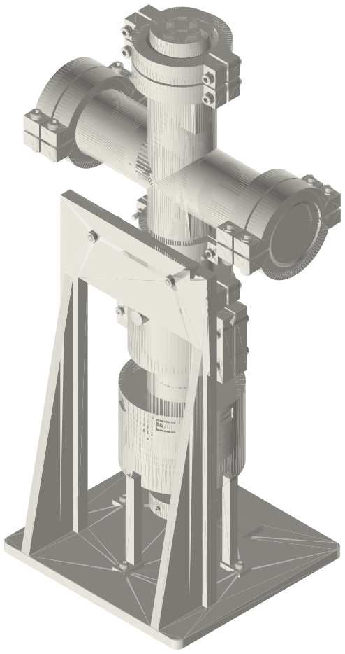
Sealed, pressurised gamma Stirling generator in 2 in tri-clamp fittings: a finned one-piece hot head in a burner shroud over a torch, a clamped power membrane under a sealed 2 in cross that holds the crank, and a 2208 gimbal motor geared 2.8 : 1 from the crankshaft inside the cross as the generator, 231 × 170 × 460 mm.
Assembly STEP (9.0 MB) · STL (10.6 MB) · 154 parts
Build order
- Frame on the bench; torch stand (post toward +Y) with two M4 × 10, torch head in the ring with three M4 set screws; shroud on its three feet with M4 × 10.
- Displacer: shell and cap, the Ø3 × 60 rod right through the cap (flush with its spigot face) on the cap's grub.
- Membrane stack: backing disc under the membrane, crosshead hub on top, three M2 × 6 from the hub into the backing disc; Ø3 × 10 pin pressed in the hub's arm.
- Hot head face up; displacer in; the rod up through the membrane stack; membrane on the head's face; cross (branches along the shaft line) on top; clamp. Jacket halves round the head with four M4 × 30, port caps in; spool hanger on the cross's lower run, bar to the wall with two M5 × 25.
- Crank: con-rods with their 623s; displacer con-rod (40) in the rod clevis on a Ø3 × 12; clevis onto the rod; diaphragm con-rod (60) on the crosshead pin. Hub web on the −X shaft with its grub, displacer pin through it and the displacer con-rod, link web, diaphragm pin through the link web and the diaphragm con-rod, hub web on the +X shaft over the pin.
- Spacers, the crank gear and flywheel discs on the shafts; each bearing plate with its two 623s over its shaft and into its branch with a Type B gasket and clamp; pocket flywheel on each shaft end; Type B gasket and flat end cap on each plate, clamp.
- Motor: adaptor on the rotor top with four M2 × 4, pinion on its stub with the grub; base to the mount face with four M3 × 6 countersunk; leads up through the plate's bore. Type B gasket, motor-mount plate onto the top of the cross with the pinion in mesh, clamp.
- Leads through the sealed pass-through in the port cap; Type B gasket and port cap on the mount plate, clamp; fill valve, gauge and relief valve in the other ports. Charge slowly (see the questions below).
Agents: each row's object has /api/geometry?object=slug and the MCP tool get_free_files; the STL list above is every part.
JSON: /api/geometry?object=list-tri-clamp-sealed-diaphragm-generator