 Xem Studiomeasured geometry
Library › Hardware › Stirling & thermoacoustic ·
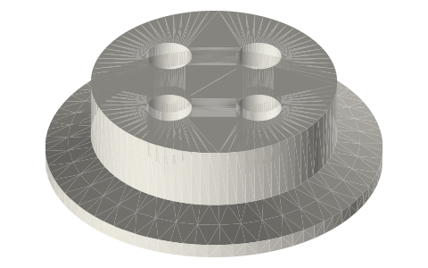
Tri-clamp port cap: 2 in, four 1/8 NPT ports for a fill valve, a gauge, a relief valve and an electrical pass-through
How do I put a fill valve, a pressure gauge, a relief valve and a wire pass-through on a tri-clamp vessel? · Hardware · basis: ISO 2852 face and 20° back exactly as the flat end cap; 1/8-27 NPT (ASME B1.20.1): major Ø10.29, hand-tight engagement L1 4.1, effective thread L2 6.7, tap drill Ø8.6 (as on this site's NPT thread envelope page)
Long Earth Society build part. The fill, gauge, relief and wire ports on my sealed generator. The engines
Exact dimensions. Every file is drawn at true size with no printing tolerance. The holes and pins that meet another part are listed below under Mating features, with the fit each joint needs; open those by your printer's or process's clearance before making the part. Mating features
- sizes
- 8 in table
Notes
- The flat end cap's profile with a Ø46.7 neck to 18 mm. Four 1/8 NPT ports on Ø24, 90° apart, each drawn as its tap drill, Ø8.6 × 10 deep from the top (the thread as the tap-drill bore, the convention of the thread envelopes on this site), then a passage on into the vessel.
- Three ports for the fill valve, the pressure gauge and the pressure relief valve (Ø3 passages). The fourth takes a sealed electrical pass-through with a 1/8 NPT male thread, for the generator's three leads; its passage is Ø6 so the leads reach it from inside.
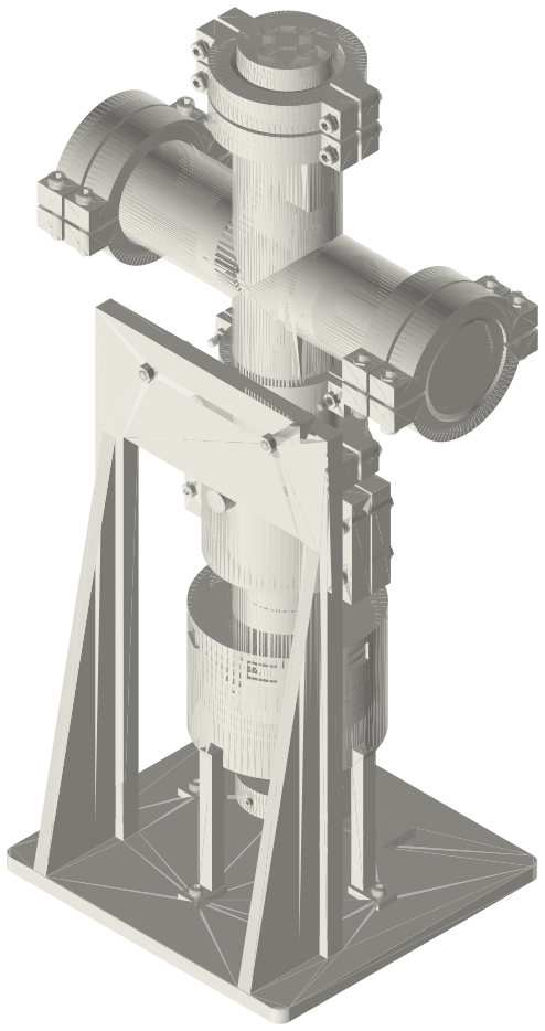
- On the sealed generator this cap sits on the motor-mount plate at the top of the cross, so all four see the crankcase, which follows the working space's mean pressure through the bleed.
- Design charge 2 bar gauge. That pressure pushes a cap off its joint with 354 N over the Ø47.5 bore, 501 N if it acts out to the gasket bead (Ø56.5); at a 3 bar relief setting 532–752 N. Every clamp, fitting, pass-through and cap on the vessel must be rated above the relief setting; I set the relief valve no higher than the lowest of those ratings.
Sizes
| feature | value |
|---|---|
| face | ISO 2852, as the 2 in flat end cap |
| height | 18.0 |
| ports | 4 × 1/8-27 NPT on Ø24, 90° apart |
| tap drill | Ø8.6 × 10 |
| thread (B1.20.1) | Ø10.29 major, L1 4.1, L2 6.7 |
| passages | Ø6 (pass-through), 3 × Ø3 |
| end force, 2 bar g | 354–501 N |
| end force, 3 bar g | 532–752 N |
Mating features
Drawn at the exact size. Open press, slide, run and socket features by your process's clearance; leave designed gaps and clamp fits as drawn.
| feature | exact | mates with | fit | files |
|---|---|---|---|---|
| cap face | ISO 2852 (as tc-cap-2in-flat) | standard clamp + Type B gasket | clamp | all |
| ports | 4 × 1/8-27 NPT, tap drill Ø8.6 × 10 (ASME B1.20.1) | fill valve, pressure gauge, relief valve, sealed electrical pass-through (1/8 NPT male) | designed | all |
| passages | Ø6 (pass-through) and 3 × Ø3 | motor leads; gas to the ports | designed | all |
Where the files are
Other publishers' files are linked, not hosted. "verify" = check the license at the link before commercial use.
| ISO (via iTeh sample) | ISO 2852 clamp liners: face profile and flange / groove diameters | standard excerpt; dimensions are facts | |
| ASME | BPE Bioprocessing Equipment (clamp fitting dimensions, tube OD and wall) | standard | ASME; dimensions are facts verify |
| ASME | ASME B1.20.1 Pipe Threads, General Purpose, Inch (NPT): 1/8-27 major Ø10.29, hand-tight engagement L1 4.1, effective thread L2 6.7; tap drill Ø8.6 as on this site's NPT thread envelopes | standard | ASME; dimensions are facts verify |
| Long Earth Society | Engine builds | web, video | LES site |
Free files
★ Free files 1 parts. Generated by Xem Studio from the standard; threads are plain cylinders at major diameter. CC BY 4.0. index.json
| port-cap-2in-4x-npt18 | 2 in port cap: tc_cap profile with a Ø46.7 neck to 18; 4 × 1/8 NPT ports on Ø24 at 90°: tap drill Ø8.6 × 10 from the top (thread as the tap-drill bore), then Ø6 (electrical pass-through, 0°) or Ø3 (fill, gauge, relief) to the recess floor | STEP · STL |
Plain text: sheet.txt · JSON: /api/geometry?object=tri-clamp-port-cap
How it fits
In these build lists
Tri-clamp sealed diaphragm generator, 2 inA sealed, pressurised gamma Stirling generator in 2 in tri-clamp: a finned one-p…You might also need
Questions
What thread are the ports?
1/8-27 NPT (ASME B1.20.1), drawn as the Ø8.6 tap drill 10 deep; the effective thread length L2 is 6.7 mm.
How do the generator's wires get out?
Through a sealed electrical pass-through screwed into the fourth 1/8 NPT port; the Ø6 passage below it leads the three motor leads up from the crankcase.
How hard does 2 bar push on a 2 in cap?
354 N over the bore, 501 N out to the gasket bead.