 Xem Studiomeasured geometry
Library › Stirling engines › Drives & mechanisms ·
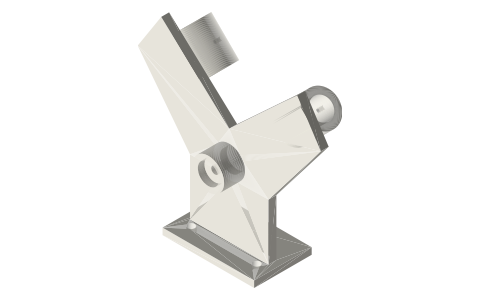
Alpha V-twin frame for two 10 mL syringes: frame, crank disc and con-rods sized so it actually runs
How do I hold two syringes and a crank together for an alpha Stirling engine? · Hardware · basis: Computed in the generator: crank throw 8, rod 60, 10 mL syringe piston (pin 8.6 above the skirt, 19 long), barrel 15.9 OD / 14.5 ID; checked over a full turn: skirt never closer than the barrel mouth, rod never within 0.5 mm of the barrel wall
Long Earth Society build part. The two-syringe alpha, complete. The engines
- sizes
- 8 in table
Notes
- Phase: in a 90° V both con-rods ride ONE crank pin, and the 90° between the cylinders is the 90° alpha phase. (A two-pin disc with pins 90° apart is for parallel cylinders; under a 90° V it would give 0° or 180° and the engine would not run.)
- Geometry: crank axis at the origin; both barrel axes pass through it at ±45°. Barrel sockets start at R45 so the piston (bottom of skirt 43.4 mm from the axis at bottom dead centre) never leaves the barrel, and with a 60 mm rod the rod swings at most ±7.7°, keeping 0.8 mm from the barrel wall.
- Along the shaft (Y): 625 · boss · 625, 2 mm spacer, crank disc (6), 1 mm spacer, rod 1 (cylinder at +45°), 1 mm spacer, rod 2 (cylinder at −45°), Ø3 × 20 pin pressed 6 mm into the disc, 3 mm collar on its end. Flywheel (nut-weighted Ø100, b5) on the other end of the Ø5 × 80 shaft behind the boss.
- Barrels slide in from the crank side, tip outward, finger flange against the socket's inner face; M3 pinch screw. Pistons: syringe-piston-10ml (no plunger). Transfer: a short tube with a mesh plug between the tips (transfer tee).
- Foot: 2 × M5 at 50 mm into a 2020 rail; mount it at the rail's end so the flywheel hangs clear. Print the frame on its back (the plate on the bed).
- LES: the two-syringe alpha, complete.
- Fits are designed in: every hole is the mating part's size plus the clearance for the joint (press 0, slide +0.2, running pin +0.3, bearing / magnet / nut pocket +0.2, large sleeve +0.3 mm on diameter), so the parts print and go together as they are, in any material. Tapped holes are 2.5 mm for M3.
Sizes
| parameter | value | note |
|---|---|---|
| crank throw | 8.0 | stroke 16 → 2.6 mL per cylinder |
| con-rod | 60.0 | Ø3 plain ends, H8/f7 |
| V angle | 90 | = phase |
| socket inner face | 45.0 | radius from crank axis |
| min skirt radius | 43.4 | ≥ barrel mouth |
| rod-to-wall margin | 0.83 | > 0 |
| shaft | Ø5 × 80 | 2 × 625 |
| rod planes (Y) | 9.5 / 15.5 | 1 mm spacers |
Where the files are
Other publishers' files are linked, not hosted. "verify" = check the license at the link before commercial use.
| Long Earth Society | Engine builds | web, video | LES site |
| Wikipedia | Stirling engine (alpha configuration) | web | CC BY-SA 4.0 (text) |
Free files
★ Free files 3 parts. Generated by Xem Studio from the standard; threads are plain cylinders at major diameter. CC BY 4.0. index.json
| alpha-frame-10ml | alpha V-twin frame: Ø5 shaft in two 625s (pockets both ends of the Ø24 boss), two 10 mL barrel sockets at ±45° whose axes meet the crank axis, inner faces at R45, M3 pinch screws, foot with 2 × M5 at 50 mm for 2020 | STEP · STL |
| alpha-crank-disc-s16 | crank disc Ø26 × 6, Ø5 bore (H7/h6), tapped M3 grub, ONE Ø3 pin at 8 mm (stroke 16): both con-rods share it | STEP · STL |
| alpha-conrod-60 | con-rod 60 mm, 8 wide × 5, Ø3 plain ends (H8/f7 running on the pins; print or make two): small end in the syringe piston's 5.4 mm fork | STEP · STL |
Plain text: sheet.txt · JSON: /api/geometry?object=alpha-v-twin-frame
How it fits
Connects to
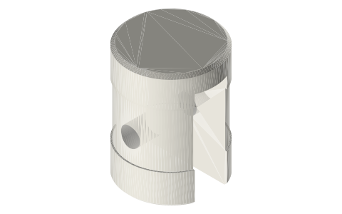 Syringe pistonstwo 10 mL pistons on the 60 mm rods
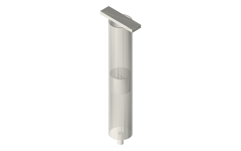 Plastic syringes 1–60 mL as pistons and cylinders10 mL barrels in the sockets
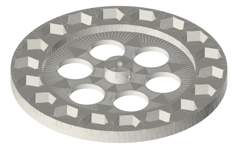 Nut-weighted flywheelsØ100 b5 behind the boss
Alternatives
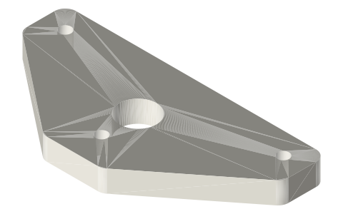 Ross yoke alpha for two parallel 10 mL syringesparallel-cylinder alpha, solved for 90°
Also needed
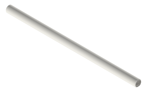 Stirling shafts and rodsØ5 × 80 crankshaft, Ø3 × 20 pin, spacers
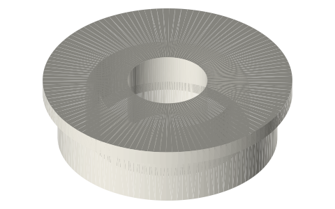 Ball bearings, 683 to 6210 and flanged F6xx2 × 625
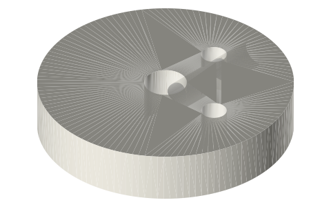 Alpha V-twintransfer tee
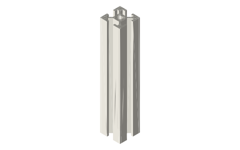 Aluminium T-slot extrusion2020 rail under the foot
In these build lists
Alpha V-twin, two 10 mL syringesTwo syringes in a 90° V on one crank pin: the alpha with no displacer, checked s…Questions
How do I get 90° phase on a two-syringe alpha Stirling?
Put the syringes in a 90° V and run both con-rods on one crank pin; the V angle is the phase. The alpha frame does exactly that.
Why a 60 mm con-rod?
A shorter rod swings further and hits the inside of a 14.5 mm syringe barrel near the mouth; at 60 mm and 16 mm stroke it clears the wall by about 0.8 mm while the piston stays fully inside the barrel.