 Xem Studiomeasured geometry
Library › Stirling engines › Drives & mechanisms ·
Stirling shafts and rods: Ø3 rods, Ø5 / Ø8 D-flat crankshafts, Ø5 tube rods, Ø3 pins, thrust spacers
What shafts and rods does a model Stirling engine need, and can I print them? · Hardware · basis: The shelf's interfaces: Ø3 displacer rods and pins, Ø5 shafts in 625 bearings, Ø8 in 608s, 5 mm tube piston rods with a Ø3.4 bore; D-flat 0.5 mm as on motor shafts so grub screws bite and the shaft cannot slip
Long Earth Society build part. The shafts, rods and pins every engine here turns on. The engines
- sizes
- 23 in table
Notes
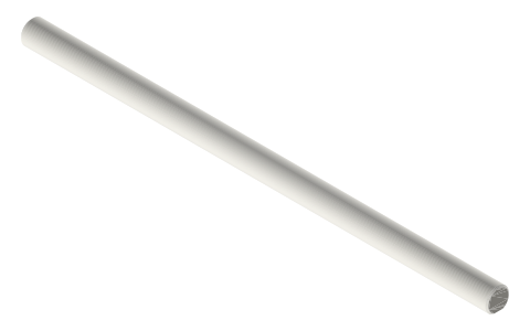
- Every rod here is a solid model: you choose walls and infill. For shafts that carry load (crankshafts, pins) print 100 % infill or 6+ walls, lying flat (the D-flat side down on the bed gives a flat, accurate grub face and puts the layers along the shaft, which is how it bends).
- Which rod goes where: Ø3 rod: displacer rod from the displacer cap through the guide, bushings or the piston's crown bushing to the rod clevis or rhombic upper yoke. Ø3 crankshaft: in the crank head's 623 towers with the Ø3-bore crank discs. Ø5 D-flat: in the 625 crank stands and rhombic plates, carrying crank discs and the nut flywheel (b5). Ø8 D-flat: in the tri-clamp crank frame's 608s with the crank webs and flywheels (b8). Ø5 tube: piston rod from the piston plug, around the displacer rod. Ø3 pins: crank, wrist and link pins.
- Printed Ø5 / Ø8 crankshafts in bearings run fine at a few hundred rpm.
- Thrust spacers set the 1 mm gaps along the shaft (tower · web · rod · web · tower · flywheel): stack 1, 2, 3 and 5 mm pieces to fill a gap.
- Lengths: 2 in gamma crankshaft Ø5 × 100 between two 625 stands with the flywheel outside; tri-clamp crank frame Ø8 × 80; rhombic gear shafts Ø5 × 80 (one × 120 to carry the flywheel); displacer rod = displacer cap to clevis plus stroke, cut a 150 or 200 to length.
- LES: the shafts the engines turn on.
- Fits are designed in: every hole is the mating part's size plus the clearance for the joint (press 0, slide +0.2, running pin +0.3, bearing / magnet / nut pocket +0.2, large sleeve +0.3 mm on diameter), so the parts print and go together as they are, in any material. Tapped holes are 2.5 mm for M3.
Sizes
| part | dia_mm | length_mm | feature | fits | steel equivalent |
|---|---|---|---|---|---|
| Ø3 rod | 3.0 | 100 | — | displacer rod; rod clevis; displacer cap | music wire / drill rod Ø3 h6 |
| Ø3 rod | 3.0 | 150 | — | displacer rod; rod clevis; displacer cap | music wire / drill rod Ø3 h6 |
| Ø3 rod | 3.0 | 200 | — | displacer rod; rod clevis; displacer cap | music wire / drill rod Ø3 h6 |
| Ø3 crankshaft | 3.0 | 40 | — | crank head 623s; crank-disc-b3 | drill rod Ø3 |
| Ø3 crankshaft | 3.0 | 60 | — | crank head 623s; crank-disc-b3 | drill rod Ø3 |
| Ø3 crankshaft | 3.0 | 80 | — | crank head 623s; crank-disc-b3 | drill rod Ø3 |
| Ø5 crankshaft | 5.0 | 80 | D 0.5 | 625 stands; rhombic gears; crank discs; flywheel b5 | Ø5 h6 ground rod |
| Ø5 crankshaft | 5.0 | 100 | D 0.5 | 625 stands; rhombic gears; crank discs; flywheel b5 | Ø5 h6 ground rod |
| Ø5 crankshaft | 5.0 | 120 | D 0.5 | 625 stands; rhombic gears; crank discs; flywheel b5 | Ø5 h6 ground rod |
| Ø5 crankshaft | 5.0 | 150 | D 0.5 | 625 stands; rhombic gears; crank discs; flywheel b5 | Ø5 h6 ground rod |
| Ø8 crankshaft | 8.0 | 80 | D 0.5 | crank frame 608s; crank webs; flywheel b8 | Ø8 h6 rod |
| Ø8 crankshaft | 8.0 | 100 | D 0.5 | crank frame 608s; crank webs; flywheel b8 | Ø8 h6 rod |
| Ø8 crankshaft | 8.0 | 120 | D 0.5 | crank frame 608s; crank webs; flywheel b8 | Ø8 h6 rod |
| Ø5 tube rod | 5.0 | 80 | Ø3.4 bore | piston plug; rhombic lower yoke; flexure stack A | K&S 5 mm brass tube |
| Ø5 tube rod | 5.0 | 120 | Ø3.4 bore | piston plug; rhombic lower yoke; flexure stack A | K&S 5 mm brass tube |
| Ø5 tube rod | 5.0 | 160 | Ø3.4 bore | piston plug; rhombic lower yoke; flexure stack A | K&S 5 mm brass tube |
| Ø3 pin | 3.0 | 12 | — | crank / wrist / link pins | dowel 3 m6 |
| Ø3 pin | 3.0 | 16 | — | crank / wrist / link pins | dowel 3 m6 |
| Ø3 pin | 3.0 | 19 | — | crank / wrist / link pins | dowel 3 m6 |
| Ø3 pin | 3.0 | 20 | — | crank / wrist / link pins | dowel 3 m6 |
| Ø3 spacers | 3 | 1 / 2 / 3 / 5 | — | between bearings, webs, rods, flywheel | washers |
| Ø5 spacers | 5 | 1 / 2 / 3 / 5 | — | between bearings, webs, rods, flywheel | washers |
| Ø8 spacers | 8 | 1 / 2 / 3 / 5 | — | between bearings, webs, rods, flywheel | washers |
Where the files are
Other publishers' files are linked, not hosted. "verify" = check the license at the link before commercial use.
| Long Earth Society | Engine builds | web, video | LES site |
Free files
★ Free files 32 parts. Generated by Xem Studio from the standard; threads are plain cylinders at major diameter. CC BY 4.0. index.json
| rod-3x100 | Ø3 × 100 solid rod: displacer rod (into the displacer cap's grub, through the guide / bushings / piston bushing, into the rod clevis) | STEP · STL |
| rod-3x150 | Ø3 × 150 solid rod: displacer rod (into the displacer cap's grub, through the guide / bushings / piston bushing, into the rod clevis) | STEP · STL |
| rod-3x200 | Ø3 × 200 solid rod: displacer rod (into the displacer cap's grub, through the guide / bushings / piston bushing, into the rod clevis) | STEP · STL |
| crankshaft-3x40 | Ø3 × 40 solid crankshaft for the crank head's 623 towers and the Ø3-bore crank discs; can engine skewer replacement | STEP · STL |
| crankshaft-3x60 | Ø3 × 60 solid crankshaft for the crank head's 623 towers and the Ø3-bore crank discs; can engine skewer replacement | STEP · STL |
| crankshaft-3x80 | Ø3 × 80 solid crankshaft for the crank head's 623 towers and the Ø3-bore crank discs; can engine skewer replacement | STEP · STL |
| crankshaft-5x80-dflat | Ø5 × 80 crankshaft with a full-length 0.5 mm D-flat (4.5 across) for the grubs; 625 crank stands, rhombic gears, crank discs, nut flywheel b5. Print flat side down | STEP · STL |
| crankshaft-5x100-dflat | Ø5 × 100 crankshaft with a full-length 0.5 mm D-flat (4.5 across) for the grubs; 625 crank stands, rhombic gears, crank discs, nut flywheel b5. Print flat side down | STEP · STL |
| crankshaft-5x120-dflat | Ø5 × 120 crankshaft with a full-length 0.5 mm D-flat (4.5 across) for the grubs; 625 crank stands, rhombic gears, crank discs, nut flywheel b5. Print flat side down | STEP · STL |
| crankshaft-5x150-dflat | Ø5 × 150 crankshaft with a full-length 0.5 mm D-flat (4.5 across) for the grubs; 625 crank stands, rhombic gears, crank discs, nut flywheel b5. Print flat side down | STEP · STL |
| crankshaft-8x80-dflat | Ø8 × 80 crankshaft with a full-length 0.5 mm D-flat (7.5 across); tri-clamp crank frame 608s, crank webs, flywheels b8. Print flat side down | STEP · STL |
| crankshaft-8x100-dflat | Ø8 × 100 crankshaft with a full-length 0.5 mm D-flat (7.5 across); tri-clamp crank frame 608s, crank webs, flywheels b8. Print flat side down | STEP · STL |
| crankshaft-8x120-dflat | Ø8 × 120 crankshaft with a full-length 0.5 mm D-flat (7.5 across); tri-clamp crank frame 608s, crank webs, flywheels b8. Print flat side down | STEP · STL |
| tube-rod-5x3.4x80 | Ø5 × Ø3.4 × 80 tube piston rod: into the piston plug socket, onto the rhombic lower yoke or the flexure collars; the Ø3 displacer rod runs inside | STEP · STL |
| tube-rod-5x3.4x120 | Ø5 × Ø3.4 × 120 tube piston rod: into the piston plug socket, onto the rhombic lower yoke or the flexure collars; the Ø3 displacer rod runs inside | STEP · STL |
| tube-rod-5x3.4x160 | Ø5 × Ø3.4 × 160 tube piston rod: into the piston plug socket, onto the rhombic lower yoke or the flexure collars; the Ø3 displacer rod runs inside | STEP · STL |
| pin-3x12 | Ø3 × 12 pin: crank pin, wrist pin, link pivot | STEP · STL |
| pin-3x16 | Ø3 × 16 pin: crank pin, wrist pin, link pivot | STEP · STL |
| pin-3x19 | Ø3 × 19 pin: crank pin, wrist pin, link pivot | STEP · STL |
| pin-3x20 | Ø3 × 20 pin: crank pin, wrist pin, link pivot | STEP · STL |
| spacer-3mm-t1 | thrust spacer for a Ø3 shaft, 1 mm: sets the 1 mm gaps between tower, web, rod and flywheel | STEP · STL |
| spacer-3mm-t2 | thrust spacer for a Ø3 shaft, 2 mm: sets the 1 mm gaps between tower, web, rod and flywheel | STEP · STL |
| spacer-3mm-t3 | thrust spacer for a Ø3 shaft, 3 mm: sets the 1 mm gaps between tower, web, rod and flywheel | STEP · STL |
| spacer-3mm-t5 | thrust spacer for a Ø3 shaft, 5 mm: sets the 1 mm gaps between tower, web, rod and flywheel | STEP · STL |
| spacer-5mm-t1 | thrust spacer for a Ø5 shaft, 1 mm: sets the 1 mm gaps between tower, web, rod and flywheel | STEP · STL |
| spacer-5mm-t2 | thrust spacer for a Ø5 shaft, 2 mm: sets the 1 mm gaps between tower, web, rod and flywheel | STEP · STL |
| spacer-5mm-t3 | thrust spacer for a Ø5 shaft, 3 mm: sets the 1 mm gaps between tower, web, rod and flywheel | STEP · STL |
| spacer-5mm-t5 | thrust spacer for a Ø5 shaft, 5 mm: sets the 1 mm gaps between tower, web, rod and flywheel | STEP · STL |
| spacer-8mm-t1 | thrust spacer for a Ø8 shaft, 1 mm: sets the 1 mm gaps between tower, web, rod and flywheel | STEP · STL |
| spacer-8mm-t2 | thrust spacer for a Ø8 shaft, 2 mm: sets the 1 mm gaps between tower, web, rod and flywheel | STEP · STL |
| spacer-8mm-t3 | thrust spacer for a Ø8 shaft, 3 mm: sets the 1 mm gaps between tower, web, rod and flywheel | STEP · STL |
| spacer-8mm-t5 | thrust spacer for a Ø8 shaft, 5 mm: sets the 1 mm gaps between tower, web, rod and flywheel | STEP · STL |
Plain text: sheet.txt · JSON: /api/geometry?object=stirling-shafts-and-rods
How it fits
Goes in or on
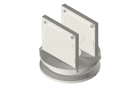 Stirling linkage fittingsØ5 shafts in the 625 crank stands; Ø3 rods in the rod clevises
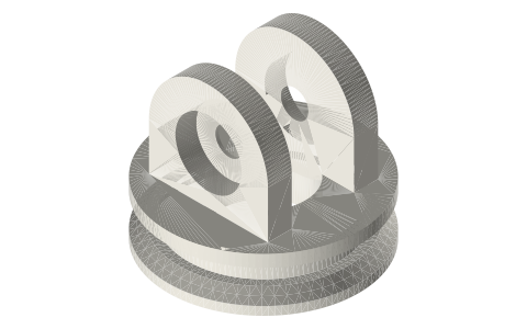 Tri-clamp power pistons and crank linkageØ8 shaft in the crank frame's 608s
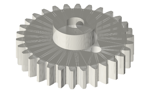 Rhombic drive kitØ5 gear shafts in the plates' 625s
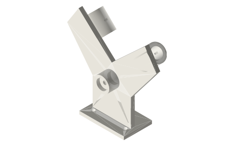 Alpha V-twin frame for two 10 mL syringesØ5 shaft in the boss; Ø3 × 20 crank pin
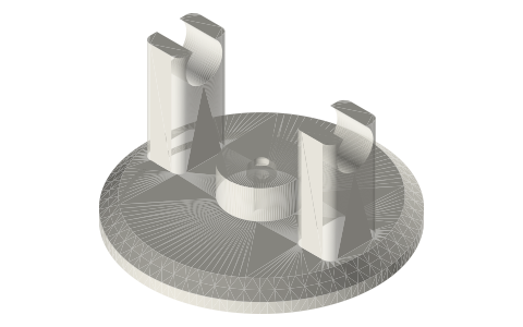 Tri-clamp displacers and engine headsØ3 displacer rod and the crank head's Ø3 shaft
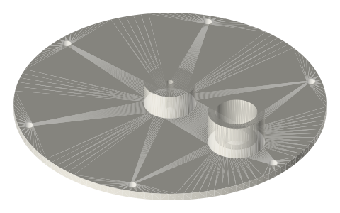 LTD Stirling kitØ3 crankshaft in the 623 stands
Connects to
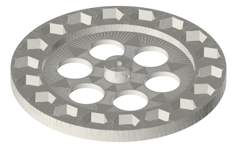 Nut-weighted flywheelsØ3 / Ø5 / Ø8 hubs on the D-flat
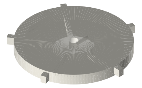 Crank discs, connecting rods and flywheels for…crank discs and flywheels
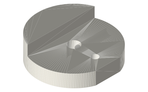 Counterweighted crank discs, crank webs and…crank discs and webs
Alternatives
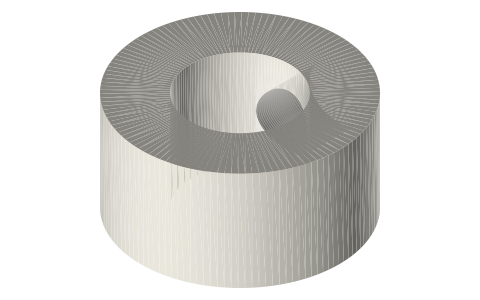 Shafts, D-flats, set-screw collars, E-clips and…steel shaft stock dimensions
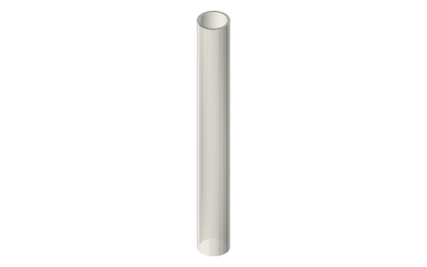 Hobby brass tube, 1/16–21/32 in and 1–12 mm,…brass tube rods
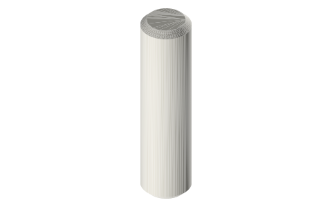 Dowel pins, 2–6 mmsteel Ø3 pins
Also needed
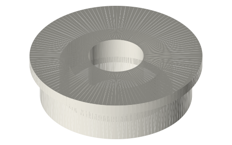 Ball bearings, 683 to 6210 and flanged F6xx623 (Ø3), 625 (Ø5), 608 (Ø8)
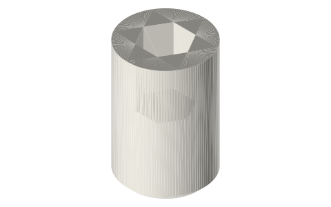 Set screws, M3–M8M3 grubs on the flat
In these build lists
Gamma Stirling, 2 in tri-clampBeta Stirling, rhombic drive, 2 in tri-clampDisplacer and piston in one bore, two counter-rotating gears: the balanced one.LTD coffee-cup engineRuns on a cup of coffee: wide thin displacer, tiny piston.Free-piston Stirling, 2 in tri-clampNo crank: displacer rod through the piston, both hung on spiral flexure stacks; …Alpha V-twin, two 10 mL syringesTwo syringes in a 90° V on one crank pin: the alpha with no displacer, checked s…Ross yoke alpha, two parallel 10 mL syringesTwo syringes side by side, one crank, a Ross yoke solved for 90° and near-straig…Questions
Can I 3D print a crankshaft for a Stirling engine?
Yes for Ø5 and Ø8 shafts at model speeds: print the D-flat shaft lying flat, flat side down, 100 % infill.
What diameter shafts does this library use?
Ø3 for displacer rods, pins and the crank head's shaft; Ø5 for crankshafts in 625 bearings; Ø8 for the tri-clamp crank frame in 608s; a 5 mm tube with a Ø3.4 bore for piston rods that carry a displacer rod inside.
Why a D-flat?
So the M3 grub screws in the crank discs, webs and flywheels bear on a flat and the part cannot slip around the shaft. 0.5 mm deep, as on motor shafts.