 Xem Studiomeasured geometry
Library › Stirling engines › Tri-clamp engine parts ·
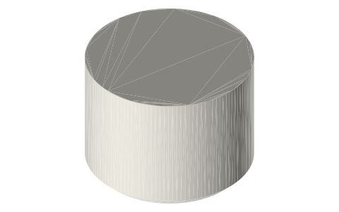
HTD cold caps: 10 in tri-clamp caps with a 2 in ferrule at the centre
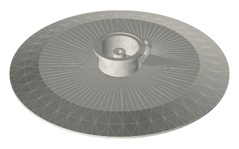
What cap closes the cold side of a 10 inch tri-clamp HTD engine? · Hardware · basis: Fabrication spec: 10 in end cap profile at 15.875 (5/8 in) instead of the standard 12.19, a 2 in L14AM7-type ferrule welded on at the centre, bosses machined; exact geometry
Long Earth Society build part. Parts of the HTD engines. The engines
Exact dimensions. Every file is drawn at true size with no printing tolerance. The holes and pins that meet another part are listed below under Mating features, with the fit each joint needs; open those by your printer's or process's clearance before making the part. Mating features
- sizes
- 1 in table
Notes
- Why thicker than a stock cap: at 6 bar gauge a stock 0.480 in cap sees 85 MPa and bows 0.35 mm; this 15.875 cap with its welded centre neck sees about 53 MPa and bows 0.16 mm, and it carries the welded ferrule, the guide boss and the NPT bosses.
- Main cap: the 2 in ferrule takes the bored power spool; inside it a Ø16 boss 20 tall carries the Ø6 displacer-rod guide (35.9 long through boss and plate); six Ø10 passages on r 16 let the gas between the chamber and the power cylinder; a 1/8 NPT boss at r 43 is the working-space gauge port.
- The flat top (inside Ø196.8, where the 20° back cone ends) carries the optional water tray.
Sizes
| part | thickness_mm | centre | ports |
|---|---|---|---|
| cold-cap-10in-main | 15.875 | 2 in ferrule, Ø6 guide, 6 × Ø10 | 1/8 NPT gauge |
Mating features
Drawn at the exact size. Open press, slide, run and socket features by your process's clearance; leave designed gaps and clamp fits as drawn.
| feature | exact | mates with | fit | files |
|---|---|---|---|---|
| face | ISO 2852 10 in | gasket-10in + 10 in clamp | clamp | all |
| 2 in ferrule face | ISO 2852 2 in | tc-gasket-2in + 2 in clamp | clamp | all |
| rod guide | Ø6 × 35.9 (plate + boss) | Ø6 displacer rod | run | cold-cap-10in-main* |
| gas passages | 6 × Ø10 on r 16 | gas (no contact) | designed | cold-cap-10in-main* |
| gauge port | 1/8-27 NPT, tap drill Ø8.6 × 10 | 1/8 NPT male | designed | all |
| flat top | inside Ø196.8 | water tray floor | designed | all |
Where the files are
Other publishers' files are linked, not hosted. "verify" = check the license at the link before commercial use.
| Steel & O'Brien | Sanitary products catalog 2024: 16AMP end caps 10 / 12 in (A 0.480, B 10.570 / 12.570 in); L14AM7 ferrules 1.500 in; clamp ratings 13MHHM, 13MHP, 13ASME | publisher's catalogue; dimensions cited, nothing copied | |
| McGraw-Hill | Young & Budynas, Roark's Formulas for Stress and Strain, 7th ed.: Table 8.1 (fixed–guided beam), Table 11.2 (circular plates under uniform pressure) | book | formulas are facts verify |
| ASME | ASME B1.20.1 Pipe Threads (NPT): 1/8-27 and 1/4-18, tap drills Ø8.6 / Ø11.1 as on this site's thread envelopes | standard | ASME; dimensions are facts verify |
| Long Earth Society | Engine builds | web, video | LES site |
Free files
★ Free files 1 parts. Generated by Xem Studio from the standard; threads are plain cylinders at major diameter. CC BY 4.0. index.json
| cold-cap-10in-main | 10 in cold cap 15.875 thick: 2 in L14AM7-type ferrule welded at the centre, Ø16 × 20 guide boss, Ø6 rod guide, six Ø10 passages on r 16, 1/8 NPT gauge boss at r 43 | STEP · STL |
Plain text: sheet.txt · JSON: /api/geometry?object=htd-cold-caps-10in
How it fits
In these build lists
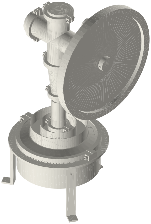
HTD engine, 10 in tri-clamp…A big flat gamma Stirling for a propane burner: a Ø240 displacer in a 10 in weld…You might also need
Questions
Why not a stock 10 in cap?
It would hold the pressure, but the centre needs a welded 2 in ferrule and bosses; I make the plate 5/8 in so the welded centre and the ports keep the stress and bow low.