 Xem Studiomeasured geometry
HTD engine, 10 in tri-clamp (high-temperature-differential flat engine)
A big flat gamma Stirling for a propane burner: a Ø240 displacer in a 10 in welded-bottom cup, a 48 mm power piston in a bored 2 in spool on the cold cap, a 3 in cross crankcase, a Ø400 flywheel and a geared generator; sealed and charged with helium.
Displacer Ø240 × 40, 8 stroke: 362 mL swept · power piston Ø48.00 × 40: 72.4 mL · dead volume 405 mL · swept/dead 0.179 · Schmidt at 650 / 350 K: 1.47 J per cycle in air at 1 bar, 7.3 J in helium at 5 bar abs · heat-transfer-limited best: air 0.39 W at the shaft near 60 rpm, helium 3.9–4.7 W near 150 rpm · generator 3.4–4.2 W at 11 V (helium) · charge 4 bar gauge helium, relief 6 bar gauge · hot face ≤ 450 °C
Exact dimensions. Every part is drawn at true size with no printing tolerance; each part's page lists its mating features and the fit each joint needs, so open those by your process's clearance before making the parts.
Long Earth Society build part. Complete parts list. The engines
53 parts, every one a file here · all STL URLs · Markdown · tick lines as you go (saved in this browser)
| subsystem | object | parts | qty | note | |
|---|---|---|---|---|---|
| None | Burner stand for a 10 in tri-clamp pot | burner-stand-10in STEP · STL | 1 | on the bench over the burner; its ring carries the 10 in clamp | |
| None | Burner shroud for a 10 in hot cup (optio | burner-shroud-10in STEP · STL | 1 | optional heat exchanger: round the cup's floor, tabs to the legs | |
| None | Socket head cap screws | shcs-m5x20 STEP · STL | 3 | optional: shroud tabs to the legs | |
| None | HTD hot cup | hot-cup-10in-60.4 STEP · STL | 1 | face up, through the ring; the displacer inside | |
| None | HTD displacers | displacer-240x40-rod6 STEP · STL | 1 | Ø240 × 40, 8 stroke, 1.5 from floor and ceiling at the ends | |
| None | HTD displacer rods | displacer-rod-6x356.7 STEP · STL | 1 | M6 into the displacer, up through guide, spool and piston to the clevis | |
| None | Sanitary clamp gaskets | gasket-10in STEP · STL | 1 | cup to cold cap | |
| None | Two-bolt high-pressure clamps for 10 and | clamp-half-10in-m8 STEP · STL | 2 | the 10 in joint, resting on the stand's ring | |
| None | Socket head cap screws | shcs-m8x40 STEP · STL | 2 | 10 in clamp bolts | |
| None | Hex nuts | nut-m8 STEP · STL | 2 | in the 10 in clamp's traps | |
| None | HTD cold caps | cold-cap-10in-main STEP · STL | 1 | 2 in ferrule up | |
| None | NPT male thread envelopes 1/8 to 1 in (A | npt-1-8-male STEP · STL | 1 | the working-space gauge's 1/8 NPT stem in the cap's boss (the gauge body is the builder's choice) | |
| None | Water tray for a 10 in cold cap (optiona | water-tray-10in STEP · STL | 1 | optional heat exchanger: on the cap's flat top round the ferrule | |
| None | Tri-clamp gasket | tc-gasket-2in STEP · STL | 2 | cap ferrule to bored spool, bored spool to reducer | |
| None | Tri-clamp clamp | clamp-half-2in STEP · STL | 4 | two 2 in joints | |
| None | Bored 2 in power spool | spool-2in-5in-bored-48.00 STEP · STL | 1 | the power cylinder | |
| None | HTD power pistons | piston-48-rod6 STEP · STL | 1 | crown down, cheeks up | |
| None | Sanitary clamp reducers | reducer-concentric-3inx2in STEP · STL | 1 | small end down | |
| None | Sanitary clamp gaskets | gasket-3in STEP · STL | 4 | reducer to cross, cross to port cap, the two branch caps | |
| None | Tri-clamp clamp | clamp-half-3in STEP · STL | 8 | four 3 in joints | |
| None | Socket head cap screws | shcs-m5x30 STEP · STL | 12 | 2 and 3 in clamp bolts | |
| None | Hex nuts | nut-m5 STEP · STL | 15 | clamp nuts (12), shroud tabs (3, optional) | |
| None | Sanitary clamp crosses (9MP) | cross-3in STEP · STL | 1 | the crankcase: run vertical, branches along the crankshaft | |
| None | 3 in crankcase caps | port-cap-3in-3x-npt14 STEP · STL | 1 | top of the cross: fill valve, gauge, relief valve | |
| None | NPT male thread envelopes 1/8 to 1 in (A | npt-1-4-male STEP · STL | 3 | the 1/4 NPT stems of the fill valve, gauge and relief valve (bodies are the builder's choice) | |
| None | 3 in crankcase caps | bearing-cap-3in-blind-6001 STEP · STL | 1 | −X branch | |
| None | 3 in crankcase caps | seal-cap-3in-6001-seal12 STEP · STL | 1 | +X branch: the shaft leaves here | |
| None | Ball bearings | bearing-6001 STEP · STL | 3 | blind cap (1), seal cap (2) | |
| None | Radial shaft seal 12 × 22 × 7 (envelope) | shaft-seal-12x22x7 STEP · STL | 1 | in the seal cap's outer housing; rated for the relief pressure | |
| None | HTD crank and linkage | shaft-12x76 STEP · STL | 1 | −X shaft | |
| None | HTD crank and linkage | shaft-12x210 STEP · STL | 1 | +X shaft | |
| None | HTD crank and linkage | crank-web-r8-b12 STEP · STL | 1 | displacer throw | |
| None | HTD crank and linkage | crank-web-link-r8-r20 STEP · STL | 1 | between the two con-rods | |
| None | HTD crank and linkage | crank-web-r20-b12 STEP · STL | 1 | piston throw | |
| None | Set screws (grub screws) | set-m4x6 STEP · STL | 2 | web hubs | |
| None | Dowel pins | dowel-5x16 STEP · STL | 4 | two crank pins, the piston pin, the clevis pin | |
| None | Ball bearings | bearing-625 STEP · STL | 4 | con-rod eyes | |
| None | HTD crank and linkage | conrod-60-625 STEP · STL | 1 | displacer | |
| None | HTD crank and linkage | conrod-237-625 STEP · STL | 1 | piston | |
| None | HTD crank and linkage | rod-clevis-6-pin5 STEP · STL | 1 | on top of the displacer rod | |
| None | Set screws (grub screws) | set-m4x4 STEP · STL | 1 | clevis to rod | |
| None | HTD generator drive | gear-m1-210t-b12 STEP · STL | 1 | on the +X shaft outside the seal cap | |
| None | Set screws (grub screws) | set-m4x8 STEP · STL | 1 | gear hub | |
| None | Ø400 flywheel on a Ø12 shaft | flywheel-400-b12 STEP · STL | 1 | on the +X shaft end | |
| None | Set screws (grub screws) | set-m6x16 STEP · STL | 2 | flywheel hub | |
| None | HTD generator drive | motor-bracket-2208-3in STEP · STL | 1 | on the seal cap's outer face | |
| None | Socket head cap screws | shcs-m4x12 STEP · STL | 3 | bracket to the seal cap | |
| None | 2208 gimbal motor | gimbal-motor-2208-envelope STEP · STL | 1 | the generator: 2208 gimbal-class outrunner (KV 128), envelope at its published size | |
| None | Countersunk socket screws | csk-m3x8 STEP · STL | 4 | motor base to the bracket, heads in the countersinks | |
| None | Step-up gears for a generator inside a 2 | pinion-adaptor-2208 STEP · STL | 1 | on the motor's rotor top | |
| None | Socket head cap screws | shcs-m2x4 STEP · STL | 4 | adaptor to the rotor | |
| None | Step-up gears for a generator inside a 2 | pinion-m1-15t-b6 STEP · STL | 1 | meshes with the 210 T gear, 14 : 1 | |
| None | Set screws (grub screws) | set-m3x3 STEP · STL | 1 | pinion grub |
Assembled engine
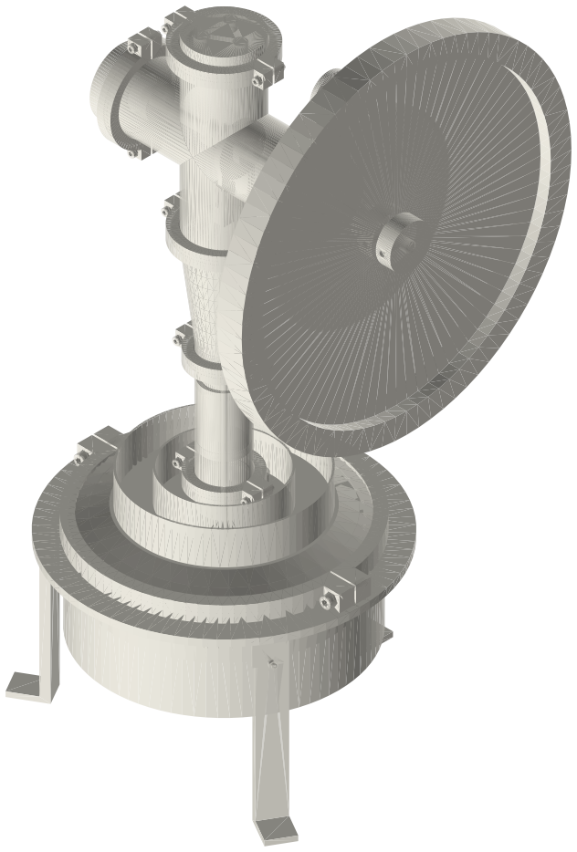
Flat gamma Stirling engine in 10 in tri-clamp fittings over a burner stand: a Ø240 displacer in a welded-bottom 10 in cup, a 2 in power cylinder and a 3 in cross crankcase on the cold cap, a Ø400 flywheel and a geared generator, 399 × 400 × 811 mm.
Assembly STEP (19.6 MB) · STL (8.5 MB) · 117 parts
Build order
Agents: each row's object has /api/geometry?object=slug and the MCP tool get_free_files; the STL list above is every part.