 Xem Studiomeasured geometry
Library › Electronics › Generators & alternators ·
Linear alternator module, 2 in tri-clamp: datasheet, closed and open frame (mass, stiffness, frequency, Bl, R, L, stroke, pressure) and test procedure
What are the clamp-in linear alternator module's own parameters, and how do I measure an engine's power with it? · Standard part · basis: My analysis of the module (tools/gen_la_module.py) at the drawn geometry; the stator and leaf models of the free-piston generator (tools/gen_fpse_gen.py)
Long Earth Society build part. The numbers of my control unit. The engines
Exact dimensions. True size, with no printing tolerance added.
- sizes
- 23 in table
Notes
- Built once and moved from engine to engine: the same mover, leaves, magnets and coil every time, so the difference in electricity is the difference in the engines. Its own numbers are below; the numbers marked model are my estimates from the drawings and cited methods, and the tests in the procedure check each of them on the built unit.
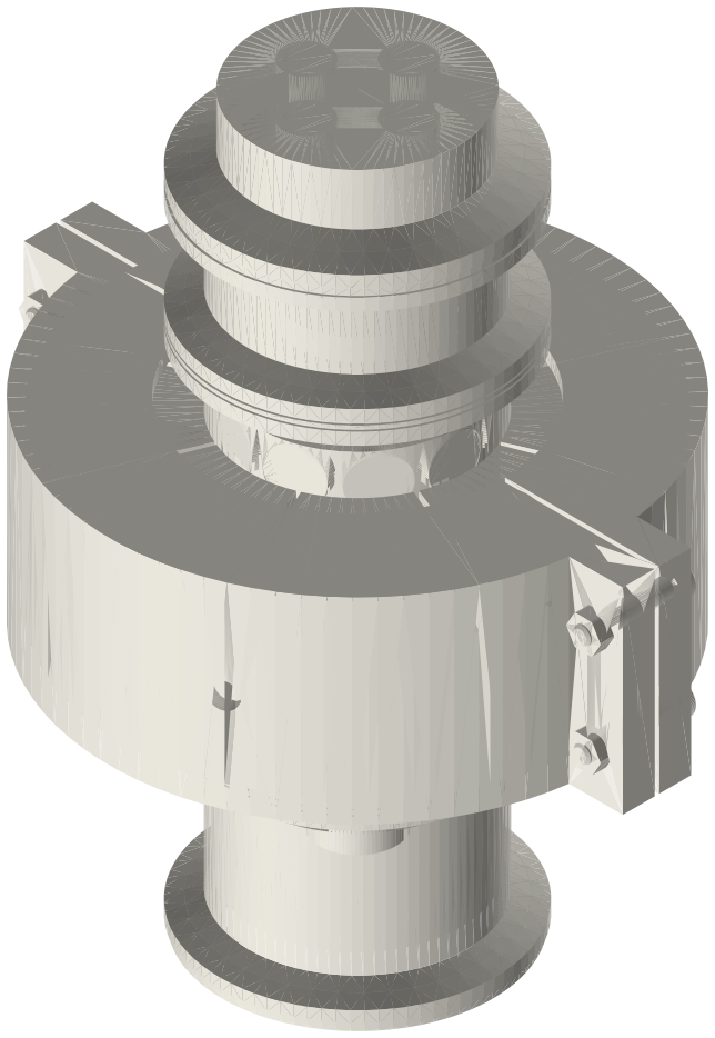
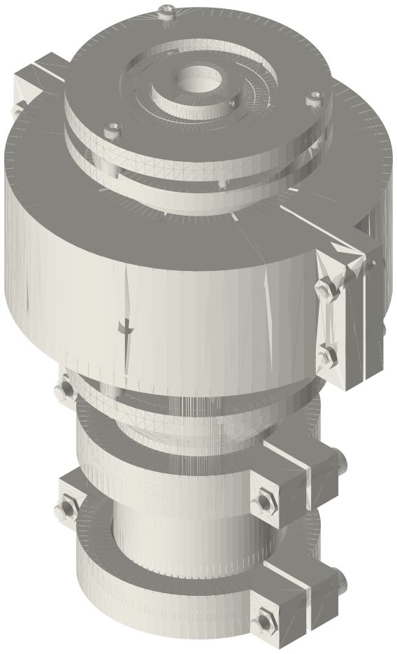
- Two versions share the face-A spool, the mover, the leaves, the magnets and the whole stator. Closed: the leaves sit in spool-to-spool joints and face B is closed by the four-port cap, a sealed bounce space you can charge; use it on charged engines, in thermoacoustic loops and rings, and in line with face B on another device. Open frame: the leaves sit on an open frame clamped on the face-A spool, the back of the piston is at the room's pressure; use it on unpressurised desk and demo engines at 1 bar, for quick swaps, and when you want to see and retune the leaves.
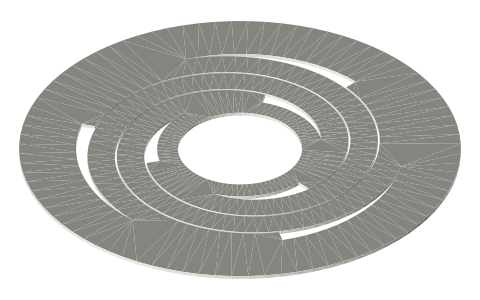
- Leaves that fit both: leaf-2in-piston-t0.8 and the soft leaf-2in-piston-t0.5 (Ø64 rim, Ø18 hub). In the closed module, and in any 2 in spool-to-spool joint, the rim goes between two half gaskets (0.45 webs beside a 0.8 leaf, 0.6 beside a 0.5); in the open frame it sits in a Ø64 × 0.8 seat under a clamp ring, on a 0.3 rim shim if it is a 0.5 leaf. Both mounts clamp the rim inside r 23.75, so stiffness and stress are the same.
- Method. Mass from the CAD volumes; leaf stiffness and stress from a 3D Euler-Bernoulli frame model of the spiral arms (rim clamped, hub rigid); bounce spring γ p A²/V (adiabatic); force constant, coil resistance and inductance from the free-piston generator's magnetic-circuit estimate of the same stator and magnets; side pull from the same estimate against the leaves' radial stiffness as a 2 × 2 lateral / tilt stiffness matrix. Linear free-piston dynamics as in Redlich & Berchowitz; Sunpower's convertors (NASA reports) are the reference for clearance-seal pistons on spiral flexures with a moving-magnet alternator.
- Electrical model of the module: an EMF E = Bl·v in series with R = 3.40 Ω and L ≈ 25 mH. A series capacitor C = 1/(ω² L) cancels L at the running frequency (20 Hz 2500 µF, 30 Hz 1111 µF, 40 Hz 625 µF, 50 Hz 400 µF, 60 Hz 278 µF, 80 Hz 156 µF); rated above the voltage across it.
- Example (model): helium 10 bar behind the piston, 35.8 Hz, ±5 mm: EMF 32.4 V peak; into 6.8 Ω with the series capacitor, 34.2 W in the load and 17.1 W in the coil, if the engine supplies that much.
- Measurement procedure (each engine the same way):
- 1. Check the unit alone (once, and after any change). Ohmmeter on the coil leads: R_c. LCR meter at the running frequency: L. Face A up and open, depth gauge on the crown: 9.00 mm below face A when centred. Turn it face A down: the mover sags by m·g/k; pass DC current through the coil until it is back at 9.00: Bl = m·g / I (m the moving mass, g 9.81 m/s²).
- 2. Resonance and damping (motoring test). Closed: face B on its cap, the charge you will test at, face A closed with a plain end cap and gasket. Open frame: face A open to the room (the leaves-only resonance) or on a plain end cap (leaves plus the trapped face-A volume). Drive the coil from an audio amplifier through a 1 Ω sense resistor and sweep the frequency: the current dips at the resonance f₀ (the EMF opposes the drive). Stop the drive and record the coil voltage as it rings down: the decay rate σ (1/s, from successive peaks) gives the open-circuit mechanical damping c_m = 2·m·σ. Repeat with one mass disc fitted: m = m_disc / ((f₀/f₁)² − 1) and k = m (2π f₀)², a check of the published mass and stiffness.
- 3. On the engine. Clamp face A to the engine (Type B gasket and clamp; high-pressure clamp on a charged engine). Closed: face B on its cap at the engine's charge, or face B into the loop. Open frame: nothing to charge; keep fingers and loose wires off the exposed leaves while it runs. Connect a non-inductive load resistor R_L (power rated above the expected output) in series with the capacitor C for the expected frequency. Never run with the coil open: the load is what holds the stroke.
- 4. Read a true-RMS voltmeter across R_L and the frequency f. Load power P = V_rms² / R_L. Current I_rms = V_rms / R_L.
- 5. Stroke check. EMF E_rms = I_rms · |R_c + R_L + j(ωL − 1/(ωC))| (= I_rms (R_c + R_L) with C tuned); amplitude X = √2 · E_rms / (Bl · ω), ω = 2π f. Keep X at or below 6 mm: if it is above, lower R_L (more load, shorter stroke) or reduce the heat.
- 6. Power the engine delivered to the piston: P_engine = P + I_rms² R_c + ½ c_m ω² X² (load, coil, and the unit's own mechanical loss from step 2 at the same charge and frequency). Compare engines at the same X, the same charge and gas, and say which numbers were measured.
- Geometry, closed: a stack of three plain 2 in spools (42 bored, 3 in bored, 25.4) with leaves 1 and 2 clamped in the two inner joints; nothing of it lies beyond face A or face B, so either face clamps on any 2 in ferrule.
- Geometry, open frame: the 42 bored spool, then the open frame on its second ferrule: frame base, leaf 1, a clamp ring on 10 mm posts, the stator sleeve with the stator, a top plate on 5 mm posts, the leaf-2 seat ring, leaf 2 and a clamp ring; 167.7 mm from face A to the top ring. Only face A is a clamp face.
Sizes
| parameter | closed (sealed bounce space) | open frame (back open to the room) | basis |
|---|---|---|---|
| use it on | charged engines (mean pressure above 1 bar), thermoacoustic loops and rings, in line with face B on another device | unpressurised engines at 1 bar (desk and demo engines), quick swaps, watching and retuning the leaves | design |
| build | 42 bored · leaf 1 in a spool joint · 3 in bored spool with the stator · leaf 2 in a spool joint · 25.4 spool · four-port cap | 42 bored spool · open frame (base, leaf seats, clamp rings, stator sleeve, posts) with both leaves exposed | drawn geometry |
| back of the piston | sealed bounce space, 156.9 cm³ at mid-stroke, chargeable through the cap | open to the room: 1492 mm² side opening (piston 1810 mm²) | drawn geometry |
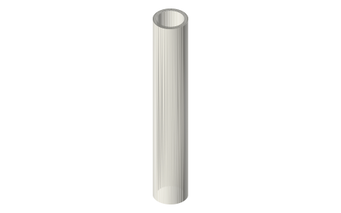
| moving mass, standard build | 865 g | 899 g (longer tube rod) | model: CAD volumes × 7.9 g/cm³ (assumed) and 7.5 g/cm³ magnets; weigh the mover |
| add-on mass disc | 24.1 g each, up to 4 | same | model: CAD volume × 7.9 g/cm³ |
| leaves | leaf-2in-piston-t0.8 (set A) or t0.5 (set B), rim between two half gaskets | the same leaves, rim in a Ø64 × 0.8 seat under a clamp ring (0.3 shim under a 0.5 leaf) | drawn geometry; both mounts clamp the rim inside r 23.75 |
| leaf axial stiffness (0.8) | 4426 N/m per leaf, 8851 N/m for the two | same | model: 3D frame of the spiral arms, E 200 GPa (assumed) |
| leaf axial stiffness (0.5, soft) | 1135 N/m per leaf, 2269 N/m for the two | same | model, as above |
| leaf radial stiffness (0.8) | 189 kN/m per leaf | same | model, as above |
| natural frequency, leaves only | 16.1 Hz (soft 8.2) | 15.8 Hz (soft 8.0) | f = √(k/m)/2π |
| gas spring on the back of the piston, γ p A²/V | 2.96 / 29.2 / 34.8 kN/m (air 1 bar / air 10 bar / helium 10 bar) | none | adiabatic gas spring; model |
| natural frequency with the gas | 18.6 / 33.4 / 35.8 Hz (bounce space at air 1 bar / air 10 bar / helium 10 bar) | leaves plus the engine's own gas on face A at 1 bar air: V_e 50 cm³ 22.6 Hz, V_e 100 cm³ 19.5 Hz, V_e 200 cm³ 17.7 Hz, V_e 400 cm³ 16.8 Hz | k_e = γ p A²/V_e added to the leaves; model (an engine's own volume and its power set the running frequency) |
| force constant Bl (= EMF constant, V·s/m) | 28.8 N/A | same | model: magnetic-circuit estimate of the generator's stator (N42 Br 1.31 T, 75 % linkage assumed); the open frame keeps the same Ø48 / Ø50.8 gap; check by the DC lift test |
| coil resistance | 3.40 Ω at 20 °C, 300 turns of 0.71 mm | same | model: wire length × IEC 60028 resistivity; measure with an ohmmeter |
| coil inductance | about 25 mH | same | estimate (gap reluctance + 30 % slot leakage); measure with an LCR meter at the running frequency |
| EMF | 0.181 V peak per mm of amplitude per Hz | same | E = Bl·ω·X |
| short-circuit damping Bl²/R | 244 N·s/m | same | model |
| stroke | ±5 mm design, ±6 mm maximum; first contact −7.05 (crown to the face-A gasket lip) / +7.10 (cup rim to leaf 1's half gasket) | ±5 / ±6 mm; first contact −7.05 (crown to the face-A gasket lip) / +7.05 (cup rim to the Type B gasket lip at the frame base) | drawn geometry; ±6 is the stator's linear range (half a tooth) |
| swept volume at ±6 | 21.7 cm³ (piston area 1810 mm²) | same | drawn geometry |
| leaf bending stress | 148 MPa at ±5, 177 MPa at ±6 (0.8); 114 MPa at ±6 (0.5) | same | model, as the stiffness |
| side pull of the stator on the mover | 55 kN/m negative radial stiffness against 379 kN/m from the two leaves 77.9 mm apart: held on the axis in shift and tilt: yes (soft leaves yes) | same side pull; leaves 93.0 mm apart: held on the axis in shift and tilt: yes (soft leaves yes) | model: the generator's side-pull estimate; 2 × 2 lateral / tilt stiffness matrix positive definite |
| pressure | mean up to 10 bar in these numbers; relief 15 bar gauge; hoop stress at relief 27.5 MPa (1.40 bored wall); 4.0 kN on each joint | 1 bar: the back of the piston is at the room's pressure; face A on an engine at 1 bar mean (standard clamp, Type B gasket) | design; clamps and gaskets rated above the pressure they see at their temperature |
| length (face A to the far end, mid-stroke) | 147.0 mm to face B; 166.7 mm to the top of the four-port cap | 167.7 mm to the upper clamp ring; the tube rod's end 169.7 (+6 at full stroke) | drawn geometry |
Where the files are
Other publishers' files are linked, not hosted. "verify" = check the license at the link before commercial use.
Xem scan
Not needed Published standard; the sheet is the geometry.
Plain text: sheet.txt · JSON: /api/geometry?object=linear-alternator-module-2in-datasheet
How it fits
In these build lists
Linear alternator module, 2 in, closed (sealed…One standard linear alternator that clamps in line on any 2 in sanitary device: …Linear alternator module, 2 in, open frame…The same linear alternator on an open frame: it clamps on the end of an unpressu…You might also need
Questions
Which numbers are measured and which are modelled?
All the numbers here are modelled from the drawings (the basis column says how). The procedure measures R, L, Bl, the resonance, the damping, the mass and the stiffness on the built unit; use the measured values when you report an engine's power.
Why not just read the load power?
The load power is what is left after the coil and the unit's own friction and gas losses. Adding those back (step 6) gives what the engine put into the piston, which is the number to compare between engines.
Can it sit in the middle of a loop?
The closed one can: take the cap off face B and clamp face B into the loop. The piston then sees the wave on both faces; the bounce-space numbers no longer apply, the rest do. The open frame has only face A.
Closed or open frame?
Open frame for unpressurised engines at 1 bar, demos, quick swaps and easy inspection and retuning of the leaves. Closed for charged engines, thermoacoustic loops and rings, and in-line use with face B on another device.