 Xem Studiomeasured geometry
Library › Electronics › Generators & alternators ·
Linear alternator module open frame, 2 in: frame base, leaf seats, clamp rings, stator sleeve and top plate
What frame carries the leaves and stator of the open-frame linear alternator module? · Hardware · basis: Design values, my geometry (tools/gen_la_module.py); the frame base's clamp face is the 2 in ISO 2852 end-cap profile drawn in tools/gen_hardware.py
Long Earth Society build part. The open frame of my clamp-in linear alternator module. The engines
Exact dimensions. Every file is drawn at true size with no printing tolerance. The holes and pins that meet another part are listed below under Mating features, with the fit each joint needs; open those by your printer's or process's clearance before making the part. Mating features
- sizes
- 6 in table
Notes
- Six parts that make the open frame of my linear alternator module. The frame base clamps on the 42 mm bored spool's second ferrule with a Type B gasket and a standard 2 in clamp, exactly as an end cap; everything else stacks on it with M3 screws, nothing around the sides: leaf 1 · lower clamp ring and its three posts · stator sleeve with the stator · top plate and its three posts · leaf-2 seat ring · leaf 2 · upper clamp ring.
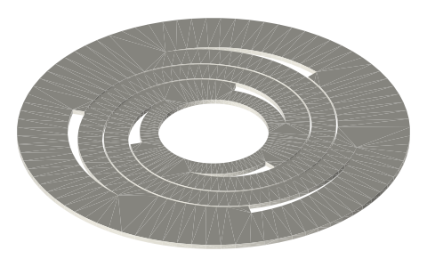
- Each leaf's Ø64 rim sits in a Ø64 × 0.8 seat (the 0.8 leaf's thickness) and a flat Ø80 clamp ring presses it down, screws on r 36 outside the leaf, so no hole goes through a leaf. The rim is clamped inside r 23.75 = 47.5 / 2 exactly as in a spool joint, so the leaves' free span, stiffness and stress are the same as in the closed module. A 0.5 soft leaf sits on a 0.3 rim shim (tuning page).
- The stator sleeve keeps the alternator's magnetic gap: its Ø50.8 outside is where the stator teeth sit (as on the bored spool) and its Ø48.00 bore leaves the same 0.5 radial gap to the Ø47 magnet carrier, so the force constant, coil and side pull are the closed module's. The bobbin goes on over the Ø64 top flange before the packs; the lower Ø80 flange carries the sleeve on the lower posts.
- Screws: 3 × M3 × 25 down through the sleeve's lower flange, the 10 mm posts and the lower clamp ring into the frame base (7 engaged in its 7.5 mm tapped holes); 3 × M3 × 12 through the top plate into the sleeve's top flange; 3 × M3 × 16 through the upper clamp ring and the seat ring into the top plate's posts. Every tapped hole is drawn at the Ø2.5 M3 tap drill.
- The back of the piston is at the room's pressure: it breathes through the frame base's Ø47.5 bore, past leaf 1 and out of the 10 mm side opening between the lower clamp ring and the sleeve (1492 mm² at the bore circle against the piston's 1810 mm²).
- Every frame part is a flat ring or a round body with flat faces at both ends and no undercut; the slopes behind the base's neck and under the sleeve's top flange are 45°. Fits are in the table; everything else is drawn at size.
Sizes
| part | what it is | size_mm | fits | qty |
|---|---|---|---|---|
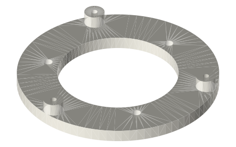
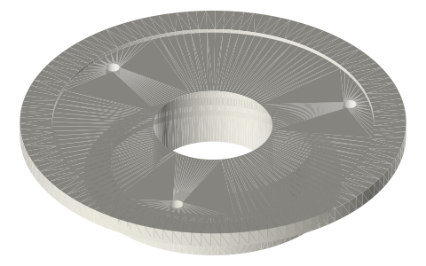
| la-frame-base-2in-ferrule | frame base (ferrule face, leaf-1 seat) | Ø80 × 28 | ISO 2852 face: clamp; seat Ø64 × 0.8: clamp (leaf rim); bore Ø47.5: designed | 1 |
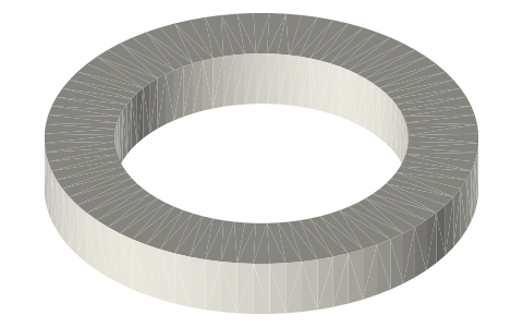
| la-frame-leaf-clamp-ring-80-posts10 | lower leaf clamp ring with posts | Ø80 × 13 | face on the leaf rim: clamp | 1 |
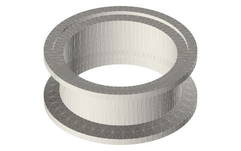
| la-frame-stator-sleeve-48x66 | stator sleeve | Ø80 × 66, bore Ø48.00 | OD Ø50.8: clamp (stator teeth); bore Ø48.00: designed (0.5 radial gap to the Ø47 carrier) | 1 |
| la-frame-stator-top-plate-80-posts5 | stator top plate with posts | Ø80 × 10 | faces: flat bolted joints | 1 |
| la-frame-leaf-seat-ring-80 | leaf-2 seat ring | Ø80 × 4 | seat Ø64 × 0.8: clamp (leaf rim) | 1 |
| la-frame-leaf-clamp-ring-80 | upper leaf clamp ring | Ø80 × 3 | face on the leaf rim: clamp | 1 |
Mating features
Drawn at the exact size. Open press, slide, run and socket features by your process's clearance; leave designed gaps and clamp fits as drawn.
| feature | exact | mates with | fit | files |
|---|---|---|---|---|
| face | ISO 2852 2 in end-cap face (recess Ø56.5 × 1.6, 20° back cone) | Type B gasket + standard 2 in clamp on the 42 mm bored spool's second ferrule | clamp | la-frame-base* |
| neck | Ø50.8 to 9.5 from the face | clamp groove room (no contact) | designed | la-frame-base* |
| leaf seat | annulus Ø47.5–Ø64 × 0.8 | leaf 1's Ø64 rim (0.8 leaf, or 0.5 leaf on a 0.3 shim), clamped by the lower clamp ring | clamp | la-frame-base* |
| bore | Ø47.5 through | collar Ø28 and tube rod pass (no contact); the piston back breathes through it | designed | la-frame-base* |
| tapped holes | 3 × Ø2.5 × 7.5 on r 36 | M3 × 25 frame screws (M3 tap drill) | designed | la-frame-base* |
| clamp face | Ø47.5–Ø80 flat | leaf rim (inside Ø64) and the seat's top face | clamp | la-frame-leaf-clamp-ring* |
| holes | 3 × Ø3.4 on r 36 (through the posts) | M3 clearance (ISO 273 medium) | designed | la-frame-leaf-clamp-ring* |
| post ends | 3 × Ø8 × 10 on r 36 | stator sleeve's lower flange | clamp | la-frame-leaf-clamp-ring-80-posts* |
| OD | Ø50.8 from s −28 to s 20 | stator pack teeth (r 25.4) and the housing halves | clamp | la-frame-stator-sleeve* |
| bore | Ø48.00 × 66 | magnet carrier Ø47 (0.5 radial gap, no contact) | designed | la-frame-stator-sleeve* |
| top flange | Ø64 | bobbin bore Ø65 passes over (no contact) | designed | la-frame-stator-sleeve* |
| lower flange | Ø80 × 5, 3 × Ø3.4 on r 36 | lower posts; M3 × 25 | clamp | la-frame-stator-sleeve* |
| tapped holes | 3 × Ø2.5 × 8 on r 28.5 | M3 × 12 from the top plate (M3 tap drill) | designed | la-frame-stator-sleeve* |
| underside | Ø48–Ø80 flat, 3 × Ø3.4 on r 28.5 | sleeve's top flange; M3 × 12 | clamp | la-frame-stator-top-plate* |
| posts | 3 × Ø8 × 5 on r 36, Ø2.5 tapped through post and plate | seat ring underside; M3 × 16 (M3 tap drill) | clamp | la-frame-stator-top-plate* |
| leaf seat | annulus Ø47.5–Ø64 × 0.8 | leaf 2's Ø64 rim, clamped by the upper clamp ring | clamp | la-frame-leaf-seat-ring* |
| holes | 3 × Ø3.4 on r 36 | M3 clearance (ISO 273 medium) | designed | la-frame-leaf-seat-ring* |
Where the files are
Other publishers' files are linked, not hosted. "verify" = check the license at the link before commercial use.
| Xem Studio | tools/gen_la_module.py: the module's geometry, masses, bounce volume, natural frequencies and every number on these pages | code | CC BY 4.0 |
| Xem Studio | tools/gen_fpse_gen.py: the free-piston generator whose stator, magnets, leaves and collars this module reuses; its leaf frame model and magnetic-circuit estimate | code | CC BY 4.0 |
| ISO (via iTeh sample) | ISO 2852 clamp liners: face profile and flange / groove diameters | standard excerpt; dimensions are facts | |
| ASME | BPE Bioprocessing Equipment (tube OD and wall, clamp fittings) | standard | ASME; dimensions are facts verify |
| Long Earth Society | Engine builds | web, video | LES site |
Free files
★ Free files 6 parts. Generated by Xem Studio from the standard; threads are plain cylinders at major diameter. CC BY 4.0. index.json
| la-frame-base-2in-ferrule | frame base: 2 in ISO 2852 end-cap face (clamps on the 42 mm spool's ferrule with a Type B gasket and a standard clamp), Ø50.8 neck to 9.5, 45° cone to Ø80, flat top at 28 with the leaf-1 rim seat (annulus Ø47.5–Ø64 × 0.8), bore Ø47.5 through, 3 × M3 tapped (Ø2.5 × 7.5) on r 36 | STEP · STL |
| la-frame-leaf-clamp-ring-80-posts10 | lower leaf clamp ring with posts: Ø80 / Ø47.5 × 3 on leaf 1's rim, three Ø8 × 10 posts on r 36 carrying the stator sleeve, Ø3.4 through each post | STEP · STL |
| la-frame-stator-sleeve-48x66 | stator sleeve: bore Ø48.00 × 66 (the magnet carrier's running gap), Ø50.8 outside under the stator teeth, lower flange Ø80 × 5 with 3 × Ø3.4 on r 36, 45° cone to the Ø64 top flange (the bobbin's Ø65 bore passes over it), 3 × M3 tapped (Ø2.5 × 8) in the top on r 28.5 | STEP · STL |
| la-frame-stator-top-plate-80-posts5 | stator top plate with posts: Ø80 / Ø48 × 5, 3 × Ø3.4 on r 28.5 to the sleeve, three Ø8 × 5 posts on r 36, M3 tapped (Ø2.5) through post and plate | STEP · STL |
| la-frame-leaf-seat-ring-80 | leaf-2 seat ring: Ø80 / Ø47.5 × 4, rim seat annulus Ø47.5–Ø64 × 0.8 in the top face, 3 × Ø3.4 on r 36 | STEP · STL |
| la-frame-leaf-clamp-ring-80 | upper leaf clamp ring: Ø80 / Ø47.5 × 3 on leaf 2's rim, 3 × Ø3.4 on r 36 | STEP · STL |
Plain text: sheet.txt · JSON: /api/geometry?object=linear-alternator-module-open-frame-2in
How it fits
In these build lists
Linear alternator module, 2 in, open frame…The same linear alternator on an open frame: it clamps on the end of an unpressu…You might also need
Questions
Why an open frame?
Nothing hides the leaves: you can watch them flex, swap a leaf or a mass disc without opening a joint, and check the mover by hand. The back of the piston is simply at the room's pressure, which is what an unpressurised engine wants.
Can the leaves go into a spool joint instead?
Yes: the same leaves (Ø64 rim) clamp between two half gaskets in any 2 in spool-to-spool joint, as in the closed module. The frame's seats are drawn to the same rim and the same clamped radius, so a leaf behaves the same in either mount.