 Xem Studiomeasured geometry
Test-tube marble engine
crank and flywheel at the end.
25 × 150 tube · 4 marbles Ø15.875 (5/8 in) · 5 mL glass syringe, plunger travel 2.1..16.6 out · rocker -7.9..7.9° · rocking pin 90° ahead · Ø100 flywheel crank · both cranks overhung
Exact dimensions. Every part is drawn at true size with no printing tolerance; each part's page lists its mating features and the fit each joint needs, so open those by your process's clearance before making the parts.
30 parts, every one a file here · all STL URLs · Markdown · tick lines as you go (saved in this browser)
| subsystem | object | parts | qty | note | |
|---|---|---|---|---|---|
| Base | Test-tube marble engine base | marble-engine-base STEP · STL | 1 | ||
| Pivot posts | Beam pivot post | pivot-post-60 STEP · STL | 2 | y ±10 | |
| Pivot pin | Dowel pins | dowel-3x30 STEP · STL | 1 | through both posts and the rocker hub | |
| Rocker | Test-tube marble engine rocker | marble-engine-rocker-25x150-glass5 STEP · STL | 1 | ||
| Displacer cylinder | Borosilicate test tubes | test-tube-25x150 STEP · STL | 1 | closed end is the hot end | |
| Displacer | Glass marbles 1/2 in | marble-5-8in STEP · STL | 4 | roll end to end as it rocks | |
| Stopper | Laboratory rubber stoppers #0–#13 (25 mm | stopper-4-bore-4 STEP · STL | 1 | #4 bored Ø4 for the 4 mm tube | |
| Transfer tube | Hobby brass tube (K&S) | brass-4mm STEP · STL | 1 | through the stopper | |
| Transfer hose | Silicone tube 1 × 3 to 10 × 14 mm (ID × | silicone-tube-4x6-50 STEP · STL | 1 | 4 mm tube to Luer cone, straight | |
| Power cylinder | Glass syringes 1–50 mL (all-glass | glass-syringe-5ml-barrel STEP · STL | 1 | in the rocker's ring | |
| Power piston | Glass syringes 1–50 mL (all-glass | glass-syringe-5ml-plunger STEP · STL | 1 | ||
| Plunger clevis | Plunger clevis for a glass syringe | plunger-clevis-glass-5ml STEP · STL | 1 | ||
| Crank stands | Crank stand for a 623 bearing | crank-stand-80 STEP · STL | 2 | 623 pockets, axis 80 above the base | |
| Bearings | Ball bearings | bearing-623 STEP · STL | 2 | ||
| Crankshaft | Crankshafts Ø3 | crankshaft-3x60 STEP · STL | 1 | along y, both cranks overhung | |
| Power crank | Crank discs Ø30 for a Ø3 crankshaft | crank-disc-b3-stroke15 STEP · STL | 1 | syringe end | |
| Flywheel crank | Flywheel crank | flywheel-crank-100-m8-b3-s15 STEP · STL | 1 | rocking end, its pin 90° ahead of the power pin | |
| Flywheel weights | Hex nuts M8 | nut-m8 STEP · STL | 6 | alternate pockets | |
| Con-rod | Con-rods with Ø3 pin ends | conrod-45 STEP · STL | 1 | power pin to plunger clevis | |
| Rocking link | Rocking link 170 mm (crank to rocker) | rocking-link-170 STEP · STL | 1 | flywheel-crank pin to the lever pin | |
| Crank pin (flywheel) | Dowel pins | dowel-3x16 STEP · STL | 1 | 10 in the hub, through the link, 1 proud | |
| Pins | Dowel pins | dowel-3x12 STEP · STL | 3 | power crank pin, clevis pin, lever pin | |
| Post screws | Socket head cap screws | shcs-m3x12 STEP · STL | 4 | ||
| Stand screws | Socket head cap screws | shcs-m3x10 STEP · STL | 4 | ||
| Nuts | Hex nuts | nut-m3 STEP · STL | 8 | in the base's pockets | |
| Grub screws | Set screws (grub screws) | set-m3x4 STEP · STL | 2 | tube ring and syringe ring | |
| Grub screw | Set screws (grub screws) | set-m3x10 STEP · STL | 1 | power crank disc | |
| Grub screw | Set screws (grub screws) | set-m3x8 STEP · STL | 1 | flywheel-crank hub | |
| Grub screw | Set screws (grub screws) | set-m3x3 STEP · STL | 1 | plunger clevis | |
| Heat | Tea lights | tea-light-38x16 STEP · STL | 1 | optional: under the closed end |
Assembled engine
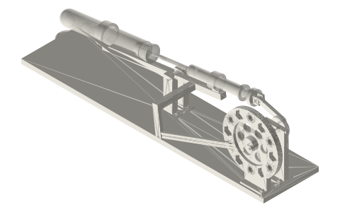
A test-tube marble Stirling engine: a 25 × 150 glass test tube with four 5/8 in marbles rocking on a pivot, joined in line to a 5 mL glass syringe, with a crank, rocking link and Ø100 flywheel crank on a flat base, 463 × 113 × 130 mm overall.
Assembly STEP (1.5 MB) · STL (3.5 MB) · 57 parts
Build order
- Base: pivot posts and crank stands with M3 screws into the nut pockets.
- Stopper bored for the 4 mm tube; marbles in the tube; stopper in; tube into the rocker's Ø25 ring; grub.
- Silicone tube over the 4 mm tube; grub. Plunger in, clevis cap on its collar.
- Rocker on the posts with a dowel-3x30. 623s, crankshaft, power crank disc at the syringe end and the flywheel crank at the other (its pin 90° ahead), six M8 nuts.
- Con-rod from the power pin to the plunger clevis; rocking link from the flywheel-crank pin to the rocker's lever pin. Tea light under the closed end.
Agents: each row's object has /api/geometry?object=slug and the MCP tool get_free_files; the STL list above is every part.