 Xem Studiomeasured geometry
Library › Electronic components › Panel cutouts ·
M12 and M8 circular sensor connectors: thread, coding A / B / D / X, pin counts and panel-mount hole sizes (+ hole gauge)
What are the M12 and M8 sensor connector codings, pin counts and standards, and what hole size does an M12 (M16 or PG9) panel-mount receptacle need? · Standard part · basis: HARTING coding table (IEC 61076-2-101 / -104 / -109 / -111 / -113 / -114), Pepperl+Fuchs mounting-hole table from two data sheets, M8Con / IO Connections / CUI sheets for threads; hole gauge file is Xem-drawn
Also called: m12 connector dimensions, m12 panel mount hole size, m12 pg9 hole 15.3, m12 m16 panel cutout, m12 coding chart, m12 a coded pin count, m12 d coded 4 pin, m12 x coded 8 pin, m8 connector thread, m8 sensor connector pinout, iec 61076-2-101, iec 61076-2-104, m12 bulkhead hole diameter, m12 receptacle mounting thread, sensor plug m12x1
Exact dimensions. Every file is drawn at true size with no tolerance added. The holes and pins that meet another part are listed below under Mating features, with the fit each joint needs; open those by your process's clearance before making the part. Mating features
- sizes
- 17 in table
Notes
- M12 and M8 are the round sensor / actuator connectors on industrial machines. The coupling thread is M12 × 1 (IEC 61076-2-101; Pepperl+Fuchs) or M8 × 1 (IEC 61076-2-104; the M8Con sheet read). The coding is the key pattern that stops mismatched plugs; it is not the pin count, though each coding has typical counts. The coding table is HARTING's (standards and applications) with pin counts as it states them; L-com's overview lists the same letters (A sensors and DC power, B PROFIBUS, D 100 Mbit Ethernet, K and S AC power, L DC power, X 10 Gigabit Ethernet) without standard numbers or pin counts.
- Panel mounting is a different thread from the coupling thread. The panel-mount (receptacle) body threads read are M16 × 1.5 or PG9 for M12 receptacles (Pepperl+Fuchs; IO Connections lists 'PG9 or M16×1.5'; a CUI D-coded sheet gives M16 × 1.5), M8 × 0.5 for M8, and PG13.5 for larger bodies. Pepperl+Fuchs prints one mounting-hole table on two data sheets (V1-PG9-500 and V1-PG13,5-Y124355): hole Ø M8 × 0.5 8.2, M12 × 1 12.2, M16 × 1.5 16.1, M20 × 1.5 20.1, PG9 15.3, PG13.5 20.5 mm (hole tolerances +0.1 to +0.2 printed; 1 × 45° chamfer). That V1-PG9-500 receptacle tightens at 3 to 4 Nm (locknut not included). The column labels in the extracted text are positional (hole Ø is column B), so confirm on the maker's drawing for your connector.
- Not in any text read: the wrench size, panel thickness range and the front / rear flange diameter of each connector; the IO Connections and Pepperl+Fuchs drawings carry those as unlabelled picture callouts. M8 mounting-hole values for M8 × 1 receptacles were also not readable (Mouser's M8Con sheet references a drawing only).
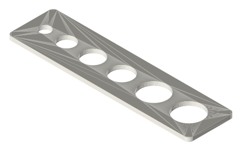
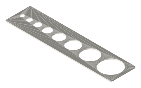
- File: a panel-hole gauge plate with the six Pepperl+Fuchs hole diameters (8.2, 12.2, 15.3, 16.1, 20.1, 20.5) to test-fit a receptacle thread before drilling a panel. Plate size, spacing and thickness are an example; the holes are the maker's.
- Related: the cable-gland page has the M12 to M63 metric thread panel holes (EN 60423); the panel-cutouts page has other connector cut-outs.
M12 and M8 circular sensor connectors: thread, coding A / B / D / X… size chart
| coding / feature | thread | standard | poles | use | panel hole Ø, mm | source note |
|---|---|---|---|---|---|---|
| A-coded M8 | M8 × 1 coupling thread | IEC 61076-2-104 | 3 to 12 (HARTING; the A-coded M8 sheet read: 3 and 4 pin) | sensor and actuator signals, field-device power | ||
| A-coded M12 | M12 × 1 coupling thread | IEC 61076-2-101 | 3 to 12 (4, 5 and 8 on the receptacle pages read) | sensor and actuator signals, field-device power | ||
| B-coded M12 | M12 × 1 coupling thread | IEC 61076-2-101 | 2, 4 or 5 | PROFIBUS fieldbus | ||
| D-coded M8 | M8 × 1 coupling thread | IEC 61076-2-114 | not stated | industrial Ethernet up to 100 Mbit/s | ||
| D-coded M12 | M12 × 1 coupling thread | IEC 61076-2-101 | 4 (a D-coded receptacle read: 4 positions, pin Ø1 mm) | industrial Ethernet up to 100 Mbit/s | ||
| K-coded M12 | M12 × 1 coupling thread | IEC 61076-2-111 | 4 + PE | power for small drives | ||
| L-coded M12 | M12 × 1 coupling thread | IEC 61076-2-111 | 4 + FE | device power at high current and voltage | ||
| P-coded M8 | M8 × 1 coupling thread | IEC 61076-2-114 | 4 | EtherCAT P data and power | ||
| S-coded M12 | M12 × 1 coupling thread | IEC 61076-2-111 | 3 + PE | power for smaller devices | ||
| X-coded M12 | M12 × 1 coupling thread | IEC 61076-2-109 | 8 | industrial Ethernet up to 10 Gbit/s | ||
| Y-coded M12 | M12 × 1 coupling thread | IEC 61076-2-113 | 8 | hybrid signal and power | ||
| mounting hole for a receptacle with M8 × 0.5 body thread | 8.2 | Pepperl+Fuchs mounting drawing (hole Ø 'B') | ||||
| mounting hole for a receptacle with M12 × 1 body thread | 12.2 | Pepperl+Fuchs mounting drawing (hole Ø 'B') | ||||
| mounting hole for a receptacle with PG9 body thread | 15.3 | Pepperl+Fuchs mounting drawing (hole Ø 'B') | ||||
| mounting hole for a receptacle with M16 × 1.5 body thread | 16.1 | Pepperl+Fuchs mounting drawing (hole Ø 'B') | ||||
| mounting hole for a receptacle with M20 × 1.5 body thread | 20.1 | Pepperl+Fuchs mounting drawing (hole Ø 'B') | ||||
| mounting hole for a receptacle with PG13.5 body thread | 20.5 | Pepperl+Fuchs mounting drawing (hole Ø 'B') |
Mating features
Drawn at the exact size. Open press, slide, run and socket features by your process's clearance (tolerances by process); leave designed gaps and clamp fits as drawn.
| feature | exact | mates with | fit | files |
|---|---|---|---|---|
| panel hole | Ø8.2 (M8×0.5), 12.2 (M12×1), 15.3 (PG9), 16.1 (M16×1.5), 20.1 (M20×1.5), 20.5 (PG13.5) | receptacle body thread of that size (maker's drawing governs panel thickness and flange) | slide | panel-hole* |
Where the files are
Other publishers' files are linked, not hosted. "verify" = check the license at the link before commercial use.
Free files
★ Free files 1 parts. Generated by Xem Studio from the standard; threads are plain cylinders at major diameter. CC BY 4.0. index.json
| panel-hole-gauge-m8-m12-m16-pg9-pg13-5-m20 | Panel-hole gauge plate for circular-connector receptacles: six through holes Ø8.2 (M8 × 0.5), 12.2 (M12 × 1), 15.3 (PG9), 16.1 (M16 × 1.5), 20.1 (M20 × 1.5), 20.5 (PG13.5), smallest first, hole diameters as in the Pepperl+Fuchs mounting table; plate 136.4 × 34.5 × 3 mm with 3 mm corners is an example | STEP · STL |
https://xemstudio.com/mcp to Claude, ChatGPT, Cursor or any MCP client (free, no account, one minute) and it can look up exact sizes, mating fits and free STEP/STL from every chat.Plain text: sheet.txt · JSON: /api/geometry?object=m12-m8-circular-sensor-connectors
Fits with
Questions
What size hole does an M12 panel receptacle need?
It depends on the body thread: Ø16.1 for M16 × 1.5, Ø15.3 for PG9 (Pepperl+Fuchs); the M12 × 1 plug thread itself is the coupling side.
What is the difference between A, B and D coded M12?
Different key patterns: A for sensors and DC power, B for PROFIBUS, D for 100 Mbit industrial Ethernet (4 pins), X for 10 Gbit Ethernet (8 pins).
What standard defines M12 connectors?
IEC 61076-2-101 (A, B, D coding); X is -2-109, K, L and S are -2-111, Y is -2-113.
What thread is an M8 sensor connector?
M8 × 1 (IEC 61076-2-104, A-coded 3 and 4 pin); the panel body thread of M8 receptacles is M8 × 0.5 with an 8.2 mm hole.