 Xem Studiomeasured geometry
Library › Hardware › Bearings, rails & motion ·
Retaining rings DIN 471 (external, for shafts): ring dimensions and groove diameter d2 × width m, 3 to 100 mm
What groove diameter and width does a DIN 471 external retaining ring (circlip) need on a shaft, and what are the ring's thickness and lug sizes? · Standard part · basis: DIN 471 tables as published by Westfield Fasteners, s / d2 / m checked against Maedler's data sheet, column meanings from fasten.it; McMaster-Carr linked for CAD
Also called: din 471, din 471 groove, external circlip groove, retaining ring groove diameter, circlip groove width, snap ring groove dimensions, din 471 table, external retaining ring dimensions, circlip groove 10mm, circlip groove 8mm, din 471 20mm, seeger ring shaft groove, wellensicherungsring
Exact dimensions. True size, with no printing tolerance added.
- sizes
- 56 in table
Notes
- DIN 471 is the external retaining ring (circlip, snap ring) for shafts: a split spring-steel ring that sits in a groove turned into the shaft. The groove is the part you design: its diameter d2, width m and depth t = (d1 − d2) / 2 are in the table, plus the edge margin n the groove needs to the shaft end. The ring's own numbers (thickness s, free inside diameter d3, lug width a and width b, lug-hole diameter d5) are there so a housing or tool clears them.
- Table: normal type, 3 to 100 mm, as printed in Westfield Fasteners' DIN 471 table (listed values for sizes 23, 27, 37, 39, 44, 46 and 47 are blank there and are not in the table). Cross-checks: s, d2 and m of nine sizes (3, 8, 10, 12, 20, 25, 40, 50, 75) agree with Maedler's data sheet; t equals (d1 − d2) / 2 on all rows; fasten.it's DIN 471 page lists the same columns (edition 04/2011, replacing 09/1981). Tolerances (d2 h10-type steps, m H13) are in the standard, not in the files. One example table elsewhere (Sunhyings) shows 9.4 instead of 9.6 for the 10 mm groove; it is labelled an example and the two maker tables agree with each other and with the existing circlip groove sizes on the shaft page, so it is not used.
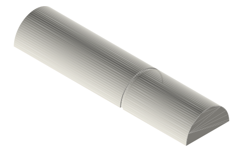
- Files: half-section groove templates for 11 common sizes: a shaft Ø d1 × 4 d1 long with the groove Ø d2 × m wide, cut in half along the axis (flat face down, so it prints and lays against a ring or caliper), nominal. The shaft length and groove position are an example (the standard fixes the groove, not the shaft); use them to check a ring or a bore on the printer before cutting steel.
- Left out: the ring outline. The lug shape, the ring's cross-section and the opening gap are drawn in the standard but the tables used here only give a, b, d3, s and d5, so a ring file would be invented; heavy-type rings (DIN 471 table 2), sizes above 100 mm, load capacities and detaching speeds.
- Inch rings: McMaster-Carr lists MS 16624 external rings (page links below) and inch internal rings; the MS 16624 / MS 16625 dimension tables were not readable here, so no inch numbers are published. McMaster's DIN 471 category carries free per-part STEP; it is linked, not copied.
Retaining rings DIN 471 (external, for shafts): ring dimensions and… size chart
| shaft d1, mm | ring thickness s, mm | ring free inner Ø d3, mm | lug width a (max), mm | ring width b (approx), mm | lug hole d5 (min), mm | groove Ø d2, mm | groove width m, mm | groove depth t, mm | edge margin n (min), mm |
|---|---|---|---|---|---|---|---|---|---|
| 3 | 0.4 | 2.7 | 1.9 | 0.8 | 1 | 2.8 | 0.5 | 0.1 | 0.3 |
| 4 | 0.4 | 3.7 | 2.2 | 0.9 | 1 | 3.8 | 0.5 | 0.1 | 0.3 |
| 5 | 0.6 | 4.7 | 2.5 | 1.1 | 1 | 4.8 | 0.7 | 0.1 | 0.3 |
| 6 | 0.7 | 5.6 | 2.7 | 1.3 | 1.2 | 5.7 | 0.8 | 0.15 | 0.5 |
| 7 | 0.8 | 6.5 | 3.1 | 1.4 | 1.2 | 6.7 | 0.9 | 0.15 | 0.5 |
| 8 | 0.8 | 7.4 | 3.2 | 1.5 | 1.2 | 7.6 | 0.9 | 0.2 | 0.6 |
| 9 | 1 | 8.4 | 3.3 | 1.7 | 1.2 | 8.6 | 1.1 | 0.2 | 0.6 |
| 10 | 1 | 9.3 | 3.3 | 1.8 | 1.5 | 9.6 | 1.1 | 0.2 | 0.6 |
| 11 | 1 | 10.2 | 3.3 | 1.8 | 1.5 | 10.5 | 1.1 | 0.25 | 0.8 |
| 12 | 1 | 11 | 3.3 | 1.8 | 1.7 | 11.5 | 1.1 | 0.25 | 0.8 |
| 13 | 1 | 11.9 | 3.4 | 2 | 1.7 | 12.4 | 1.1 | 0.3 | 0.9 |
| 14 | 1 | 12.9 | 3.5 | 2.1 | 1.7 | 13.4 | 1.1 | 0.3 | 0.9 |
| 15 | 1 | 13.8 | 3.6 | 2.2 | 1.7 | 14.3 | 1.1 | 0.35 | 1.1 |
| 16 | 1 | 14.7 | 3.7 | 2.2 | 1.7 | 15.2 | 1.1 | 0.4 | 1.2 |
| 17 | 1 | 15.7 | 3.8 | 2.3 | 1.7 | 16.2 | 1.1 | 0.4 | 1.2 |
| 18 | 1.2 | 16.5 | 3.9 | 2.4 | 2 | 17 | 1.3 | 0.5 | 1.5 |
| 19 | 1.2 | 17.5 | 3.9 | 2.5 | 2 | 18 | 1.3 | 0.5 | 1.5 |
| 20 | 1.2 | 18.5 | 4 | 2.6 | 2 | 19 | 1.3 | 0.5 | 1.5 |
| 21 | 1.2 | 19.5 | 4.1 | 2.7 | 2 | 20 | 1.3 | 0.5 | 1.5 |
| 22 | 1.2 | 20.5 | 4.2 | 2.8 | 2 | 21 | 1.3 | 0.5 | 1.5 |
| 24 | 1.2 | 22.2 | 4.4 | 3 | 2 | 22.9 | 1.3 | 0.55 | 1.7 |
| 25 | 1.2 | 23.2 | 4.4 | 3 | 2 | 23.9 | 1.3 | 0.55 | 1.7 |
| 26 | 1.2 | 24.2 | 4.5 | 3.1 | 2 | 24.9 | 1.3 | 0.55 | 1.7 |
| 28 | 1.5 | 25.9 | 4.7 | 3.2 | 2 | 26.6 | 1.6 | 0.7 | 2.1 |
| 29 | 1.5 | 26.9 | 4.8 | 3.4 | 2 | 27.6 | 1.6 | 0.7 | 2.1 |
| 30 | 1.5 | 27.9 | 5 | 3.5 | 2 | 28.6 | 1.6 | 0.7 | 2.1 |
| 32 | 1.5 | 29.6 | 5.2 | 3.6 | 2.5 | 30.3 | 1.6 | 0.85 | 2.6 |
| 34 | 1.5 | 31.5 | 5.4 | 3.8 | 2.5 | 32.3 | 1.6 | 0.85 | 2.6 |
| 35 | 1.5 | 32.2 | 5.6 | 3.9 | 2.5 | 33 | 1.6 | 1 | 3 |
| 36 | 1.75 | 33.2 | 5.6 | 4 | 2.5 | 34 | 1.85 | 1 | 3 |
| 38 | 1.75 | 35.2 | 5.8 | 4.2 | 2.5 | 36 | 1.85 | 1 | 3 |
| 40 | 1.75 | 36.5 | 6 | 4.4 | 2.5 | 37.5 | 1.85 | 1.25 | 3.8 |
| 42 | 1.75 | 38.5 | 6.5 | 4.5 | 2.5 | 39.5 | 1.85 | 1.25 | 3.8 |
| 45 | 1.75 | 41.5 | 6.7 | 4.7 | 2.5 | 42.5 | 1.85 | 1.25 | 3.8 |
| 48 | 1.75 | 44.5 | 6.9 | 5 | 2.5 | 45.5 | 1.85 | 1.25 | 3.8 |
| 50 | 2 | 45.8 | 6.9 | 5.1 | 2.5 | 47 | 2.15 | 1.5 | 4.5 |
| 52 | 2 | 47.8 | 7 | 5.2 | 2.5 | 49 | 2.15 | 1.5 | 4.5 |
| 55 | 2 | 50.8 | 7.2 | 5.4 | 2.5 | 52 | 2.15 | 1.5 | 4.5 |
| 56 | 2 | 51.5 | 7.3 | 5.5 | 2.5 | 53 | 2.15 | 1.5 | 4.5 |
| 58 | 2 | 53.5 | 7.3 | 5.6 | 2.5 | 55 | 2.15 | 1.5 | 4.5 |
| 60 | 2 | 55.8 | 7.4 | 5.8 | 2.5 | 57 | 2.15 | 1.5 | 4.5 |
| 62 | 2 | 57.8 | 7.5 | 6 | 2.5 | 59 | 2.15 | 1.5 | 4.5 |
| 63 | 2 | 58.8 | 7.6 | 6.2 | 2.5 | 60 | 2.15 | 1.5 | 4.5 |
| 65 | 2.5 | 60.8 | 7.8 | 6.3 | 3 | 62 | 2.65 | 1.5 | 4.5 |
| 68 | 2.5 | 63.5 | 8 | 6.5 | 3 | 65 | 2.65 | 1.5 | 4.5 |
| 70 | 2.5 | 65.5 | 8.1 | 6.6 | 3 | 67 | 2.65 | 1.5 | 4.5 |
| 72 | 2.5 | 67.5 | 8.2 | 6.8 | 3 | 69 | 2.65 | 1.5 | 4.5 |
| 75 | 2.5 | 70.5 | 8.4 | 7 | 3 | 72 | 2.65 | 1.5 | 4.5 |
| 78 | 2.5 | 73.5 | 8.6 | 7.3 | 3 | 75 | 2.65 | 1.5 | 4.5 |
| 80 | 2.5 | 74.5 | 8.6 | 7.4 | 3 | 76.5 | 2.65 | 1.75 | 5.3 |
| 82 | 2.5 | 76.5 | 8.7 | 7.6 | 3 | 78.5 | 2.65 | 1.75 | 5.3 |
| 85 | 3 | 79.5 | 8.7 | 7.8 | 3.5 | 81.5 | 3.15 | 1.75 | 5.3 |
| 88 | 3 | 82.5 | 8.8 | 8 | 3.5 | 84.5 | 3.15 | 1.75 | 5.3 |
| 90 | 3 | 84.5 | 8.8 | 8.2 | 3.5 | 86.5 | 3.15 | 1.75 | 5.3 |
| 95 | 3 | 89.5 | 9.4 | 8.6 | 3.5 | 91.5 | 3.15 | 1.75 | 5.3 |
| 100 | 3 | 94.5 | 9.6 | 9 | 3.5 | 96.5 | 3.15 | 1.75 | 5.3 |
Where the files are
Other publishers' files are linked, not hosted. "verify" = check the license at the link before commercial use.
Free files
★ Free files 11 parts. Generated by Xem Studio from the standard; threads are plain cylinders at major diameter. CC BY 4.0. index.json
| groove-gauge-shaft-8mm-din-471 | Half-section (cut along the axis, flat face down) of a Ø8 × 32 mm shaft with the DIN 471 ring groove: groove Ø7.6 (d2) × 0.9 mm wide (m), groove centre 12 mm from one end; nominal values, no chamfers; length and groove position are an example, d1, d2 and m are the standard's | STEP · STL |
| groove-gauge-shaft-10mm-din-471 | Half-section (cut along the axis, flat face down) of a Ø10 × 40 mm shaft with the DIN 471 ring groove: groove Ø9.6 (d2) × 1.1 mm wide (m), groove centre 15 mm from one end; nominal values, no chamfers; length and groove position are an example, d1, d2 and m are the standard's | STEP · STL |
| groove-gauge-shaft-12mm-din-471 | Half-section (cut along the axis, flat face down) of a Ø12 × 48 mm shaft with the DIN 471 ring groove: groove Ø11.5 (d2) × 1.1 mm wide (m), groove centre 18 mm from one end; nominal values, no chamfers; length and groove position are an example, d1, d2 and m are the standard's | STEP · STL |
| groove-gauge-shaft-15mm-din-471 | Half-section (cut along the axis, flat face down) of a Ø15 × 60 mm shaft with the DIN 471 ring groove: groove Ø14.3 (d2) × 1.1 mm wide (m), groove centre 22.5 mm from one end; nominal values, no chamfers; length and groove position are an example, d1, d2 and m are the standard's | STEP · STL |
| groove-gauge-shaft-17mm-din-471 | Half-section (cut along the axis, flat face down) of a Ø17 × 68 mm shaft with the DIN 471 ring groove: groove Ø16.2 (d2) × 1.1 mm wide (m), groove centre 25.5 mm from one end; nominal values, no chamfers; length and groove position are an example, d1, d2 and m are the standard's | STEP · STL |
| groove-gauge-shaft-20mm-din-471 | Half-section (cut along the axis, flat face down) of a Ø20 × 80 mm shaft with the DIN 471 ring groove: groove Ø19 (d2) × 1.3 mm wide (m), groove centre 30 mm from one end; nominal values, no chamfers; length and groove position are an example, d1, d2 and m are the standard's | STEP · STL |
| groove-gauge-shaft-25mm-din-471 | Half-section (cut along the axis, flat face down) of a Ø25 × 100 mm shaft with the DIN 471 ring groove: groove Ø23.9 (d2) × 1.3 mm wide (m), groove centre 37.5 mm from one end; nominal values, no chamfers; length and groove position are an example, d1, d2 and m are the standard's | STEP · STL |
| groove-gauge-shaft-30mm-din-471 | Half-section (cut along the axis, flat face down) of a Ø30 × 120 mm shaft with the DIN 471 ring groove: groove Ø28.6 (d2) × 1.6 mm wide (m), groove centre 45 mm from one end; nominal values, no chamfers; length and groove position are an example, d1, d2 and m are the standard's | STEP · STL |
| groove-gauge-shaft-35mm-din-471 | Half-section (cut along the axis, flat face down) of a Ø35 × 140 mm shaft with the DIN 471 ring groove: groove Ø33 (d2) × 1.6 mm wide (m), groove centre 52.5 mm from one end; nominal values, no chamfers; length and groove position are an example, d1, d2 and m are the standard's | STEP · STL |
| groove-gauge-shaft-40mm-din-471 | Half-section (cut along the axis, flat face down) of a Ø40 × 160 mm shaft with the DIN 471 ring groove: groove Ø37.5 (d2) × 1.85 mm wide (m), groove centre 60 mm from one end; nominal values, no chamfers; length and groove position are an example, d1, d2 and m are the standard's | STEP · STL |
| groove-gauge-shaft-50mm-din-471 | Half-section (cut along the axis, flat face down) of a Ø50 × 200 mm shaft with the DIN 471 ring groove: groove Ø47 (d2) × 2.15 mm wide (m), groove centre 75 mm from one end; nominal values, no chamfers; length and groove position are an example, d1, d2 and m are the standard's | STEP · STL |
https://xemstudio.com/mcp to Claude, ChatGPT, Cursor or any MCP client (free, no account, one minute) and it can look up exact sizes, mating fits and free STEP/STL from every chat.Plain text: sheet.txt · JSON: /api/geometry?object=retaining-rings-din-471-external
Fits with
Questions
What groove does a 10 mm DIN 471 ring need?
Groove diameter 9.6 mm, 1.1 mm wide (depth 0.2 mm); the ring is 1.0 mm thick with a 9.3 mm free inside diameter.
How is the groove depth found?
t = (d1 − d2) / 2: for a 20 mm shaft with a 19.0 mm groove that is 0.5 mm. The groove width m is the ring thickness + 0.1 mm up to 1.75 mm rings and + 0.15 mm from 2.0 mm rings up.
Does McMaster-Carr sell DIN 471 rings?
Yes: it has a DIN 471 retaining ring category and MS 16624 inch external rings; both are linked on this page.