 Xem Studiomeasured geometry
Library › Stirling engines › Drives & mechanisms ·
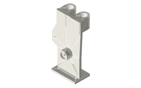
Ross yoke alpha frame for two 10 mL syringes
What frame holds two parallel syringes and a crank for a Ross yoke Stirling engine? · Hardware · basis: Solved Ross linkage: barrel axes 40 apart, socket inner faces 63 above the crank axis, rocking-link post at (−40, 20); 625 pockets at the bearing OD
Long Earth Society build part. The parallel-cylinder alpha, solved. The engines
Exact dimensions. Every file is drawn at true size with no printing tolerance. The holes and pins that meet another part are listed below under Mating features, with the fit each joint needs; open those by your printer's or process's clearance before making the part. Mating features
- sizes
- 6 in table
Notes
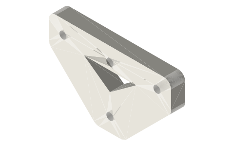
- The one-piece frame of the Ross yoke alpha: 83 × 53.45 × 148. A Ø24 boss carries the Ø5 crankshaft in two 625 bearings (Ø16 pockets, fit: press) with a Ø5.6 passage between them.
- Two Ø15.9 barrel sockets (fit: socket) on parallel axes 40 mm apart; their inner faces sit 63 mm above the crank axis, where the syringe finger flanges seat. The lowest piston skirt comes to 62.1 mm, so the pistons never leave the barrels; M3 pinch screws in Ø2.5 holes.
- A post at (−40, 20) has a Ø3 hole (fit: press) for the rocking-link pin. The foot has 2 × Ø5.5 at 50 mm for M5 into a 2020 rail.
Sizes
| parameter | value |
|---|---|
| outline | 83 × 53.45 × 148 |
| barrel sockets | 2 × Ø15.9, axes 40 apart |
| socket inner face | 63 above crank axis |
| bearing pockets | 2 × Ø16 (625) |
| rocking-link post | Ø3 at (−40, 20) |
| foot | 2 × Ø5.5 at 50 |
Mating features
Drawn at the exact size. Open press, slide, run and socket features by your process's clearance; leave designed gaps and clamp fits as drawn.
| feature | exact | mates with | fit | files |
|---|---|---|---|---|
| barrel sockets | Ø15.9 | 10 mL syringe barrel | socket | ross-frame-* |
| bearing pockets | Ø16 | 625 bearing | press | ross-frame-* |
| frame-post pin hole | Ø3 | Ø3 × 20 pin | press | ross-frame-* |
| shaft passage between pockets | Ø5.6 | Ø5 shaft (no contact) | designed | ross-frame-* |
| pinch-screw holes | Ø2.5 | M3 tap drill | designed | ross-frame-* |
| foot holes | Ø5.5 | M5 clearance (ISO 273) | designed | ross-frame-* |
Where the files are
Other publishers' files are linked, not hosted. "verify" = check the license at the link before commercial use.
| Wikipedia | Ross yoke | web | CC BY-SA 4.0 (text) |
| Long Earth Society | Engine builds | web, video | LES site |
Free files
★ Free files 1 parts. Generated by Xem Studio from the standard; threads are plain cylinders at major diameter. CC BY 4.0. index.json
| ross-frame-2x-10ml | Ross alpha frame: Ø5 shaft in two 625s, two 10 mL barrel sockets on parallel axes 2 × 20 = 40 mm apart (inner faces 63 mm above the crank axis), rocking-link post at (-40, 20), foot 2 × M5 at 50 mm for 2020 | STEP · STL |
Plain text: sheet.txt · JSON: /api/geometry?object=ross-yoke-frame
How it fits
Parts that fit it
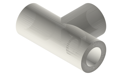 Transfer tee for 4 × 6 mm tubebetween the Ross alpha's syringe tips
Goes in or on
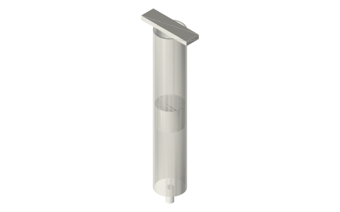 Plastic syringes 1–60 mL as pistons and cylinderstwo 10 mL barrels in the Ø15.9 sockets
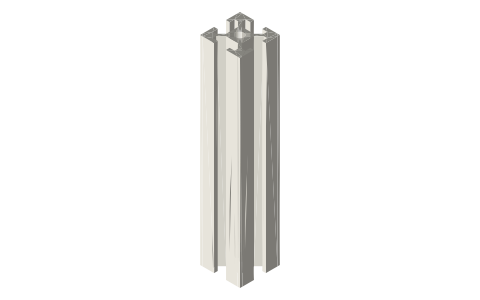 Aluminium T-slot extrusion2 × M5 into 2020
Connects to
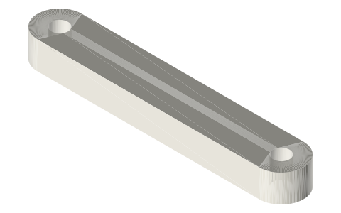 Ross yoke rocking link, 40 mmØ3 × 20 pin in the post
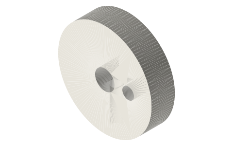 Ross yoke crank disc Ø24, 6 mm throwon the Ø5 shaft in the boss
Alternatives
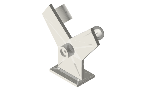 Alpha V-twin frame for two 10 mL syringes at 90°V-twin alpha on one crank pin
Also needed
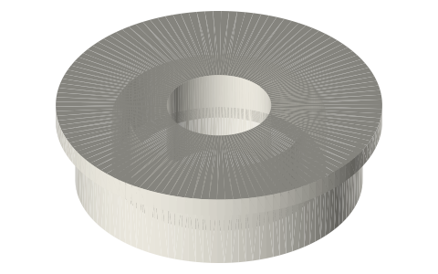 Ball bearings, 683 to 6210 and flanged F6xx2 × 625
In these build lists
Ross yoke alpha, two parallel 10 mL syringesTwo 10 mL syringe barrels side by side on a Ross yoke: a = h gives 90° between t…You might also need
Questions
How far apart are the syringes on the Ross yoke frame?
40 mm between parallel axes; turn both finger flanges front-to-back so they do not touch.
How does the Ross frame mount?
Two M5 screws through the Ø5.5 foot holes, 50 mm apart, into 2020 extrusion.