 Xem Studiomeasured geometry
Library › Hardware › Sanitary clamp fittings ·
Two-bolt high-pressure clamps for 10 and 12 in tri-clamp joints
What clamp holds a 10 inch tri-clamp joint under pressure? · Hardware · basis: Groove as the site's tri-clamp clamps (the ISO 2852 rim's 20° back cone mirrored, contact after 0.4, 0.6 squeeze), on the 10 / 12 in rims; two halves, one M8 bolt at each split
Exact dimensions. Every file is drawn at true size with no printing tolerance. The holes and pins that meet another part are listed below under Mating features, with the fit each joint needs; open those by your printer's or process's clearance before making the part. Mating features
- sizes
- 2 in table
Notes
- Published ratings (Steel & O'Brien, psi at 70 °F / 250 °F): 10 in 13MHP high-pressure 200 / 125, 13ASME double-bolt 161 / 145, 13MHHM wing-nut 75 / 40; 12 in 150 / 100, 102 / 92, 50 / 25. Holland and Shaw rate their hinged wing-nut clamps lower still (10 in 40 / 30 psi). A wing-nut clamp is not a pressure clamp at these sizes.
- This clamp is a Xem Studio design, not a copy of any of those: the end load on a 10 in joint at 6 bar gauge is 32.1 kN (pressure out to the groove diameter), the 20° groove turns it into a hoop tension of 1859 N at each split (F tan 20° / 2π), 51 MPa on an M8's stress area before the seating load. The section behind the groove is 6 mm; size the clamp's own material for that tension at the joint's temperature, or use a rated commercial high-pressure clamp of the same rim size.
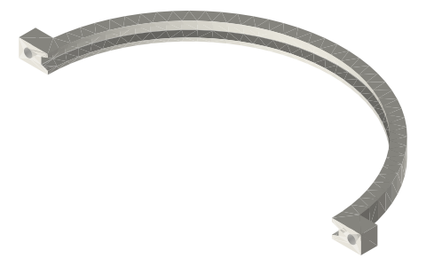
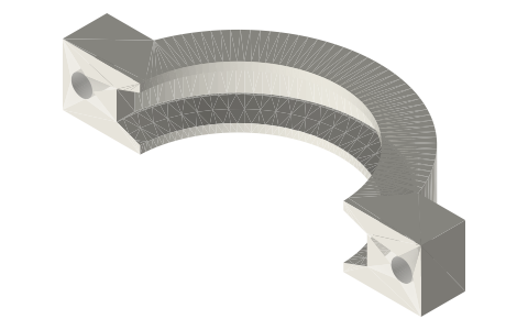
- Each half: lug at each end with an M8 clearance hole (Ø9, ISO 273 medium) along the split and a 13 AF nut trap 6.8 deep on the lug's outer face; M8 × 40 heads on one half, nuts in the other's traps. Tighten evenly until the halves just meet.
Sizes
| size_in | clamp_od_mm | width_mm | bolt_spacing_mm | bolts | 13MHP_psi_70F_250F | 13MHHM_psi_70F_250F |
|---|---|---|---|---|---|---|
| 10 | 282.5 | 19.43 | 298.5 | 2 × M8 × 40 + nuts | 200 / 125 | 75 / 40 |
| 12 | 333.3 | 19.43 | 349.3 | 2 × M8 × 40 + nuts | 150 / 100 | 50 / 25 |
Mating features
Drawn at the exact size. Open press, slide, run and socket features by your process's clearance; leave designed gaps and clamp fits as drawn.
| feature | exact | mates with | fit | files |
|---|---|---|---|---|
| groove | 20° walls on the rims, contact after 0.4 radial, 0.6 squeeze | two 10 / 12 in ferrule or cap rims | clamp | all |
| bolt holes | Ø9 (M8 clearance, ISO 273 medium) | shcs-m8x40 | designed | all |
| nut traps | 13 AF × 6.8 | M8 nut (ISO 4032) | socket | all |
| bore | tube OD + 2 | tube (no contact) | designed | all |
Where the files are
Other publishers' files are linked, not hosted. "verify" = check the license at the link before commercial use.
| Steel & O'Brien | Sanitary products catalog 2024: 16AMP end caps 10 / 12 in (A 0.480, B 10.570 / 12.570 in); L14AM7 ferrules 1.500 in; clamp ratings 13MHHM, 13MHP, 13ASME | publisher's catalogue; dimensions cited, nothing copied | |
| Holland Applied Technologies | Sanitary tri-clamp fittings: EG14AM7 ferrules 8 / 10 / 12 in (1.500, bore 9.732 / 11.732 in, tube 10.000 / 12.000 in); EG16A caps (10.570 / 12.570 in) | publisher's catalogue; dimensions cited, nothing copied | |
| Shaw Stainless & Alloy | Sanitary clamp data sheet: EG14AM7 ferrules (bore 9.732 / 11.732 in), EG16A caps 10.570 / 12.570 in, 13MHHM ratings | publisher's data sheet; dimensions cited, nothing copied | |
| ISO (via iTeh sample) | ISO 2852 clamp liners: face profile (2.85 rim, 1.6 recess, 20° back) and land width | standard excerpt; dimensions are facts | |
| McGraw-Hill | Young & Budynas, Roark's Formulas for Stress and Strain, 7th ed.: Table 8.1 (fixed–guided beam), Table 11.2 (circular plates under uniform pressure) | book | formulas are facts verify |
Free files
★ Free files 2 parts. Generated by Xem Studio from the standard; threads are plain cylinders at major diameter. CC BY 4.0. index.json
| clamp-half-10in-m8 | 10 in two-bolt clamp half (two per joint): 20° groove, contact after 0.4, 0.6 squeeze; section 6 behind the groove; Ø282.5 × 19.43 wide; M8 × 40 through Ø9 at x ±149.24, nut in a 13 AF trap 6.8 deep | STEP · STL |
| clamp-half-12in-m8 | 12 in two-bolt clamp half (two per joint): 20° groove, contact after 0.4, 0.6 squeeze; section 6 behind the groove; Ø333.3 × 19.43 wide; M8 × 40 through Ø9 at x ±174.64, nut in a 13 AF trap 6.8 deep | STEP · STL |
Plain text: sheet.txt · JSON: /api/geometry?object=sanitary-clamp-bolted-clamps-10-12in
How it fits
In these build lists
HTD engine, 10 in tri-clamp…A big flat gamma Stirling for a propane burner: a Ø240 displacer in a 10 in weld…You might also need
Questions
What pressure does a 10 in tri-clamp take?
Depends on the clamp: published 10 in ratings run from 40–75 psi for wing-nut clamps to 200 psi (70 °F) for a high-pressure bolted clamp. Gasket, clamp and fittings all have to be rated above the relief setting.