 Xem Studiomeasured geometry
Library › Stirling engines › Thermoacoustic & fluidyne ·
Thermoacoustic bore spacers and liners for 2 in tri-clamp spools: 8.4, 60 and 61.7 mm
How do I hold heat exchangers, a regenerator or a stack at the right place inside a 2 inch tri-clamp spool? · Hardware · basis: ASME BPE 2 in bore Ø47.5; ISO 2852 Type B lip 1.95 past the face; inside Ø44 = the regenerator cage bore; lengths from the engine layouts in tools/gen_ta_family.py
Long Earth Society build part. The spacers that hold my thermoacoustic cores together. The engines
Exact dimensions. Every file is drawn at true size with no printing tolerance. The holes and pins that meet another part are listed below under Mating features, with the fit each joint needs; open those by your printer's or process's clearance before making the part. Mating features
- sizes
- 3 in table
Notes
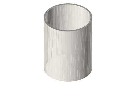
- Thin tubes at the spool bore (Ø47.5 outside, Ø44 inside) that stand between the parts of a thermoacoustic core and hold each one where the acoustic design wants it. Their ends bear on the exchangers' 1.0 mm outer ring and on the gasket lip, so the whole stack is held between the two gasket lips of the spool with nothing loose.
- 8.4: from a gasket lip to an exchanger at 10.35 mm from the face, so the exchanger sits under a 14 mm water jacket that starts 9.35 mm from the face (clear of the clamp).
- 61.7: the loop core's thermal buffer tube liner. In a 6 in spool the stack of parts is lip, 8.4 spacer, exchanger 10, buffer tube 61.7, hot exchanger 10, regenerator 40, exchanger 10, 8.4 spacer, lip: exactly the 148.5 mm between the two lips.
- 60: the hot-cavity liner of the finned standing-wave head; it holds the hot exchanger 60 mm off the closed end, which in the model lowers the half-wave engine's onset from about 680 °C (exchanger on the closed end) to about 271 °C.
- Fits: outside slide in the bore; inside is gas passage; the end faces are flat rings.
Sizes
| file | outside_mm | inside_mm | length_mm | use |
|---|---|---|---|---|
| ta-spacer-2in-8.4 | 47.5 | 44.0 | 8.4 | end spacer |
| ta-spacer-2in-60 | 47.5 | 44.0 | 60.0 | hot-cavity liner |
| ta-spacer-2in-61.7 | 47.5 | 44.0 | 61.7 | thermal buffer tube |
Mating features
Drawn at the exact size. Open press, slide, run and socket features by your process's clearance; leave designed gaps and clamp fits as drawn.
| feature | exact | mates with | fit | files |
|---|---|---|---|---|
| outside | Ø47.5 | 2 in tri-clamp spool / head bore | slide | all |
| inside | Ø44 | gas passage (no contact) | designed | all |
| end faces | flat ring Ø44–Ø47.5 | heat-exchanger outer ring, regenerator cage end, Type B gasket lip | designed | all |
| length | 8.4 / 60 / 61.7 | positions of the exchangers, stack and regenerator in the layout | designed | all |
Where the files are
Other publishers' files are linked, not hosted. "verify" = check the license at the link before commercial use.
| Long Earth Society | Engine builds | web, video | LES site |
Free files
★ Free files 3 parts. Generated by Xem Studio from the standard; threads are plain cylinders at major diameter. CC BY 4.0. index.json
| ta-spacer-2in-8.4 | Ø47.5 / Ø44 × 8.4: end spacer: from the Type B gasket lip (1.95 inside the face) to an exchanger at 8.0 | STEP · STL |
| ta-spacer-2in-60 | Ø47.5 / Ø44 × 60: hot-cavity liner of the standing-wave head: closed end to the hot exchanger | STEP · STL |
| ta-spacer-2in-61.7 | Ø47.5 / Ø44 × 61.7: thermal buffer tube liner of the loop core: hot exchanger to the secondary ambient exchanger | STEP · STL |
Plain text: sheet.txt · JSON: /api/geometry?object=thermoacoustic-bore-spacer
How it fits
In these build lists
Thermoacoustic traveling-wave loop, 2 in…A looped traveling-wave thermoacoustic engine in 2 in tri-clamp, torch-heated, w…Thermoacoustic traveling-wave loop, 2 in…The looped traveling-wave thermoacoustic engine with the free-piston's flexure-s…Thermoacoustic-Stirling hybrid loop with…The looped traveling-wave engine with a flat membrane clamped in the loop to sto…Thermoacoustic standing-wave engine,…A propane-fired standing-wave thermoacoustic engine in 2 in tri-clamp: one-piece…Thermoacoustic standing-wave engine, half-wave,…The propane standing-wave engine as a half-wave: closed at both ends, a 40 mm lo…Thermoacoustic standing-wave engine, half-wave,…The propane standing-wave engine as a half-wave with the free-piston's linear al…You might also need


Questions
Why does the buffer tube have a liner?
It is what the hot exchanger and the regenerator stand on: without it they would slide down the empty buffer tube.
Do the spacers change the acoustics?
Slightly: the gas passage is Ø44 instead of Ø47.5 over their length; the model on the build lists includes it.