 Xem Studiomeasured geometry
Library › Stirling engines › Tri-clamp engine parts ·
Linear-alternator stator that clamps round a 2 in tri-clamp tube: four coils outside the pressure wall
How do I take electricity out of a pressurised free-piston engine without a wire through the wall? · Hardware · basis: Coil window and pitch from the alternator design in tools/gen_ta_power.py; gap field from a magnetic-circuit estimate
Used in Long Earth Society builds. Thermoacoustic engine spool (aluminum) · Designing a free-piston Stirling engine
Exact dimensions. Every file is drawn at true size with no printing tolerance. The holes and pins that meet another part are listed below under Mating features, with the fit each joint needs; open those by your printer's or process's clearance before making the part. Mating features
- sizes
- 6 in table
Notes
- The coils sit outside the honed spool: a split bobbin clamps on the Ø50.8 tube with four 14 mm bays at the magnet rows' 32 mm pitch; the coils are wound in place, alternate hands, and joined in series; a split return-path shell (Ø66 / Ø74) clamps over them with three M4 × 16 and nuts each side. The shell has to carry the magnets' flux back; what it is made of is the builder's choice within that.
- The spool wall (1.40 after honing) and a 0.5 bobbin wall sit in the magnetic gap: the wall must not carry magnetic flux, or it short-circuits the magnets. In the 25 Hz field the eddy-current loss in a 1.4 mm wall is a fraction of a watt.
- Estimate: gap field 0.29 T (Br 1.3 T magnets, magnetic-circuit estimate with a 0.8 leakage factor), 369 turns of 0.45 mm wire per coil, Bl ≈ 79 T·m, coil resistance ≈ 31 Ω, inductance ≈ 132 mH; damping available Bl²/R ≈ 203 N·s/m. Measure Bl (EMF ÷ velocity) on the built engine; the model's power scales with it.
- No electrical pass-through, no wire in the gas: the generator's pressure boundary is only tri-clamp joints.
- Fits: bobbin bore clamps the tube (the 1 mm split is the take-up); shell bore clamps the bobbin flanges; ear holes are M4 clearance.
Sizes
| part | value |
|---|---|
| bays | 4 × 14 at 32 |
| coil | Ø65.8 / Ø51.8 |
| shell | Ø74 / Ø66 × 112 |
| turns per coil | 369 |
| Bl | ≈ 79 T·m |
| coil resistance | ≈ 31 Ω (all four) |
Mating features
Drawn at the exact size. Open press, slide, run and socket features by your process's clearance; leave designed gaps and clamp fits as drawn.
| feature | exact | mates with | fit | files |
|---|---|---|---|---|
| bobbin bore | Ø50.8 | 2 in tube outside (honed spool) | clamp | stator-bobbin-* |
| bobbin flanges and dividers | Ø66.0 | return-shell bore Ø66.0 | clamp | stator-bobbin-* |
| split | 1.0 total (0.5 per half) | the other half | clamp | all |
| coil bays | 4 × 14 wide, Ø51.8–Ø66 | coils wound in place (Ø51.8 / Ø65.8 winding) | designed | all |
| coil to shell | 0.1 radial | return-shell bore | designed | stator-coil-* |
| ear holes | 6 × Ø4.5 | M4 clearance (ISO 273 medium) | designed | stator-iron-* |
Where the files are
Other publishers' files are linked, not hosted. "verify" = check the license at the link before commercial use.
| Xem Studio | tools/gen_ta_power.py: the network model and every dimension on this page | code | CC BY 4.0 |
| Long Earth Society | Engine builds | web, video | LES site |
Free files
★ Free files 3 parts. Generated by Xem Studio from the standard; threads are plain cylinders at major diameter. CC BY 4.0. index.json
| stator-bobbin-half-2in-112 | bobbin half (y ≥ 0.5): wall Ø50.8 / Ø51.8, end flanges and dividers to Ø66, four 14 mm coil bays at 32 pitch, 112 long | STEP · STL |
| stator-coil-2in-14x7 | coil winding volume Ø65.8 / Ø51.8 × 14: about 369 turns of 0.45 mm wire | STEP · STL |
| stator-iron-half-2in-112 | return-path shell half (y ≥ 0.5) Ø74 / Ø66 × 112, ears x ±36..46 with Ø4.5 at x ±41.5, z 14, 56, 98 | STEP · STL |
Plain text: sheet.txt · JSON: /api/geometry?object=canned-linear-alternator-stator-2in
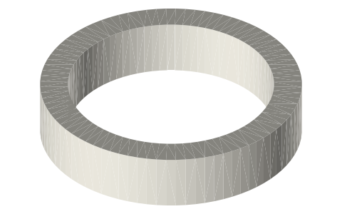
How it fits
In these build lists
Thermoacoustic-Stirling ring generator, three 2…A double-acting thermoacoustic-Stirling generator in 2 in tri-clamp: three cores…Thermoacoustic-Stirling engine with twin…Backhaus & Swift's thermoacoustic-Stirling torus in 2 in tri-clamp with two oppo…You might also need
Questions
Why outside the tube?
Then the only things in the pressurised gas are the moving magnets: no feedthrough to seal, and the coils are cooled by the room.
How are the coils joined?
In series, alternate hands, because the rows under them alternate N and S: all four voltages then add.