 Xem Studiomeasured geometry
Thermoacoustic-Stirling ring generator, three 2 in units, pressurised
A double-acting thermoacoustic-Stirling generator in 2 in tri-clamp: three cores and three free-piston alternators in a loop, charged with helium, one propane / butane torch under a drum.
3 units · 20 bar helium · 25 Hz · onset 67 °C with the alternators open, 550 °C on the design load · ≈ 90 W electric for ≈ 341 W into the hot exchangers (27 %) at ±8 mm (model)
Exact dimensions. Every part is drawn at true size with no printing tolerance; each part's page lists its mating features and the fit each joint needs, so open those by your process's clearance before making the parts.
Used in Long Earth Society builds. Custom high-temperature thermoacoustic engine (final design)
53 parts, every one a file here · all STL URLs · Markdown · tick lines as you go (saved in this browser)
| subsystem | object | parts | qty | note | |
|---|---|---|---|---|---|
| None | Tri-clamp spools to a custom length (fab | spool-2in-340.7mm STEP · STL | 3 | core, one per unit: plain 2 in tube with full ferrules; exchangers, regenerator and buffer-tube liner inside | |
| None | Thermoacoustic bore spacers and liners f | ta-spacer-2in-8.4 STEP · STL | 6 | gasket lip to each ambient exchanger, both ends of each core | |
| None | Thermoacoustic slotted exchanger insert | hx-insert-2in-14 STEP · STL | 6 | main ambient (top) and secondary ambient (bottom) exchanger of each core | |
| None | Regenerator screen disc | screen-disc-47.5-m100 STEP · STL | 1500 | regenerator: 500 per core, 100 mm of 100-mesh × 0.10 screen | |
| None | Thermoacoustic slotted exchanger insert | hx-insert-2in-12 STEP · STL | 3 | hot exchanger, under each regenerator | |
| None | Thermoacoustic buffer-tube liner | tbt-liner-2in-180 STEP · STL | 3 | thermal buffer tube: hot exchanger down to the secondary exchanger | |
| None | Tri-clamp honed cylinder spool | spool-2in-6in-honed-48.00 STEP · STL | 3 | piston cylinder under each core | |
| None | Free-piston mover for a 2 in honed spool | mover-core-2in-130 STEP · STL | 3 | mover core: the piston's magnetic return path and crown | |
| None | Free-piston mover for a 2 in honed spool | mover-sleeve-48x130 STEP · STL | 3 | mover sleeve: the running surface in the honed bore | |
| None | Neodymium block magnets | magnet-block-30x10x4 STEP · STL | 144 | 48 per mover: four rows of 12, rows alternately N and S outward | |
| None | Linear-alternator stator that clamps rou | stator-bobbin-half-2in-112 STEP · STL | 6 | two halves round each honed spool's tube | |
| None | Linear-alternator stator that clamps rou | stator-coil-2in-14x7 STEP · STL | 12 | four per alternator, wound in place, alternate hands, in series | |
| None | Linear-alternator stator that clamps rou | stator-iron-half-2in-112 STEP · STL | 6 | return-path shell halves, clamp the bobbin to the tube | |
| None | Socket head cap screws | shcs-m4x16 STEP · STL | 18 | return-shell ears, three each side | |
| None | Tri-clamp flexure carrier | flexure-carrier-2in-60 STEP · STL | 3 | under each cylinder: flexure stack A on its upper ledge, B on its lower | |
| None | Planar spiral flexure bearing leaves | flexure-40-3arm-w1.6-t0.5 STEP · STL | 12 | two per stack, opposite spiral hand | |
| None | Flexure stack spacer ring | spacer-40-t2 STEP · STL | 6 | between the leaf rims | |
| None | Flexure rim clamp plate | clamp-plate-40 STEP · STL | 6 | on each stack's rims | |
| None | Flexure hub washer | hub-clamp-40-b4 STEP · STL | 6 | between the leaf hubs | |
| None | Socket head cap screws | shcs-m3x10 STEP · STL | 18 | stack rims into the carrier ledges (tapped M3) | |
| None | Threaded rod | rod-m4x195.9 STEP · STL | 3 | mover crown (tapped M4) down through both stacks | |
| None | Hex nuts | nut-m4 STEP · STL | 39 | hub nuts (4 per rod), return-shell ears (6 per unit), drum tabs (3), hangers (2 per hanger) | |
| None | Flat washers | washer-m4 STEP · STL | 12 | under each hub nut | |
| None | Tri-clamp end caps with a welded boss (f | cap-2in-x-0.75in-ferrule STEP · STL | 6 | top of each core and bottom of each carrier: the ¾ in lines join here | |
| None | Tri-clamp gasket | tc-gasket-2in STEP · STL | 12 | Type B profile at every 2 in joint, rated above the relief setting at the joint's temperature | |
| None | Sanitary clamp elbows | elbow-90-0.75in STEP · STL | 12 | four per line | |
| None | Sanitary clamp spools | spool-0.75in-3in STEP · STL | 6 | bottom run and the riser's lowest spool | |
| None | Sanitary clamp spools | spool-0.75in-6in STEP · STL | 3 | top of each riser | |
| None | Tri-clamp spools to a custom length (fab | spool-0.75in-146.7mm STEP · STL | 3 | riser between the tee and the cross | |
| None | Sanitary clamp tees and short-outlet tee | tee-0.75in STEP · STL | 3 | fill branch | |
| None | Sanitary clamp crosses (9MP) | cross-0.75in STEP · STL | 3 | gauge and relief branches | |
| None | Tri-clamp end caps with a welded boss (f | cap-0.75in-x-1-4npt STEP · STL | 9 | close the tee and cross branches; each carries a 1/4 NPT instrument | |
| None | NPT male thread envelopes 1/8 to 1 in (A | npt-1-4-male STEP · STL | 9 | 1/4 NPT stems of the fill valve, pressure gauge and relief valve on each line | |
| None | Sanitary clamp gaskets | gasket-0.75in STEP · STL | 42 | Type B profile at every ¾ in joint, rated above the relief setting | |
| None | Thermoacoustic burner drum | drum-ring-lower STEP · STL | 1 | round the three hot zones; its flue comes down to the torch | |
| None | Thermoacoustic burner drum | drum-ring-upper STEP · STL | 1 | vents in the top | |
| None | Socket head cap screws | shcs-m4x20 STEP · STL | 9 | drum tabs (3), hangers (2 per hanger) | |
| None | Torch stand for a horizontal tri-clamp h | torch-stand-40 STEP · STL | 1 | on the bench under the flue; the heat source is a propane / butane torch head in its ring | |
| None | Set screws (grub screws) | set-m4x10 STEP · STL | 3 | centre the torch head | |
| None | Thermoacoustic water jacket | ta-jacket-half-2in-14 STEP · STL | 12 | optional: over the two ambient exchangers of each core, two halves each | |
| None | Socket head cap screws | shcs-m4x25 STEP · STL | 12 | optional: jacket ears | |
| None | Hex nuts | nut-m4 STEP · STL | 12 | optional: jacket ears | |
| None | Thermoacoustic fin sleeve | fin-sleeve-half-2in-34 STEP · STL | 6 | optional: over each hot exchanger inside the drum, two halves each | |
| None | Socket head cap screws | shcs-m4x16 STEP · STL | 6 | optional: fin-sleeve ears | |
| None | Hex nuts | nut-m4 STEP · STL | 6 | optional: fin-sleeve ears | |
| None | 2020 aluminum extrusion | 2020-200 STEP · STL | 12 | per stand: two rails on the bench, two uprights | |
| None | L corner brackets for 20 | corner-bracket-20 STEP · STL | 12 | two per upright | |
| None | Button head socket screws | button-m5x10 STEP · STL | 24 | bracket screws, a washer each | |
| None | Flat washers | washer-m5 STEP · STL | 24 | ||
| None | Drop-in T-nuts for 20 | tnut-dropin-20-m5 STEP · STL | 30 | 8 per stand for the brackets, 2 for its hanger | |
| None | Spool hanger collars | hanger-2in-tab STEP · STL | 3 | round each flexure carrier's neck: the column hangs from it | |
| None | Spool hanger collars | hanger-2in-plain STEP · STL | 3 | ||
| None | Socket head cap screws | shcs-m5x16 STEP · STL | 6 | hanger bars into the uprights |
Assembled engine
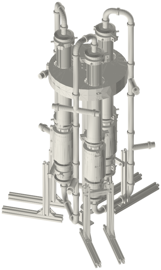
A pressurised double-acting thermoacoustic-Stirling generator in 2 in tri-clamp: three vertical columns on a 160 mm circle, each a plain core spool with exchanger inserts and a screen regenerator over a honed cylinder whose free piston carries the alternator magnets, coils clamped outside, flexure carriers below, joined in a ring by ¾ in lines with fill, gauge and relief ports, one burner drum and flue over a torch; about 526 × 473 × 792 mm.
Assembly STEP (7.0 MB) · STL (22.5 MB) · 2112 parts
Build order
- Stands: three short 2020 stands, one behind each column, rails on the bench; each column hangs from a hanger round its flexure carrier's neck.
- Cores (bottom face down): 8.4 spacer, secondary exchanger, 180 liner, hot exchanger, 500 screen discs, main ambient exchanger, 8.4 spacer; gaskets and 2 in caps with the ¾ in ferrule on top.
- Drum lower half over the three cores' lower ends before the cylinders go on; fin sleeves (optional) on the hot zones; drum upper half from the top; tabs bolted.
- Power modules: mover (48 magnets on the core, sleeve over them, M4 rod into the crown) into each honed spool; carrier with stacks A and B threaded on the rod, nuts set so the leaves are flat at mid-stroke; stator halves round each spool, coils wound in place, return shell clamped; each module clamped under its core, a capped ¾ in ferrule under each carrier.
- ¾ in lines: from under each column, elbow, 3 in spool, elbow up, riser (3 in spool, tee, custom spool, cross, 6 in spool), two elbows over into the top of the next column; caps with the fill valve on the tee, gauge and relief valve on the cross.
- Water jackets (optional) over the ambient exchangers; torch stand under the flue; charge each line through its fill valve to 20 bar; leak-check; connect each alternator through its capacitor to its load before lighting the torch.
Agents: each row's object has /api/geometry?object=slug and the MCP tool get_free_files; the STL list above is every part.